Universal lock

A technology of road lock and function, applied in the field of multi-purpose lock

Inactive Publication Date: 2015-04-29
多玛德国有限公司
View PDF3 Cites 0 Cited by
  • Summary
  • Abstract
  • Description
  • Claims
  • Application Information

AI Technical Summary

Problems solved by technology

In these different types of locks, it has proven to be a disadvantage that, to insert the locks into these moving walls, these locks require special, different treatments of the moving walls

Method used


Image

  • Universal lock
  • Universal lock
  • Universal lock

Examples


Embodiment Construction

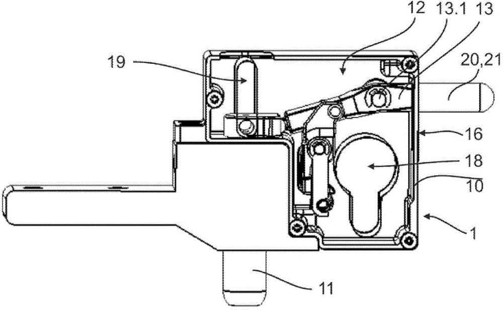
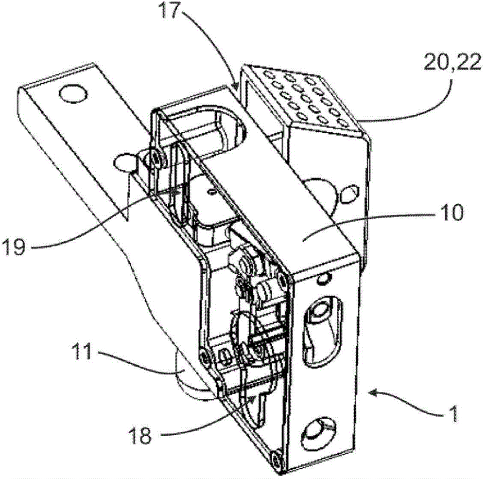
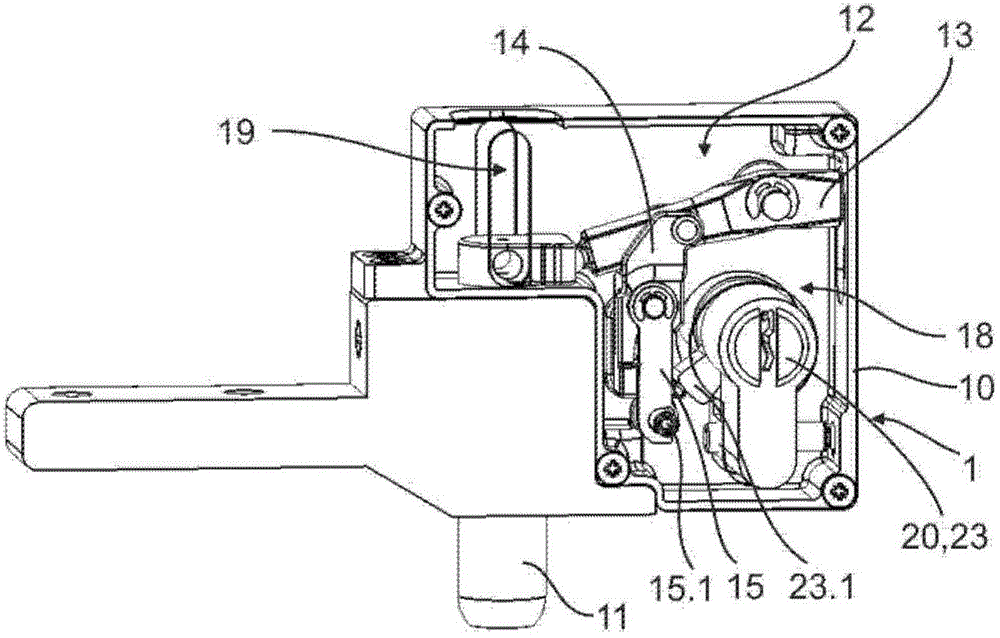
[0023] Figure 1 to Figure 3 A lock 1 according to the invention is shown, which is advantageously configured as a multipurpose lock and is adapted to accommodate moving walls of different lock mechanisms 12 . The lock 1 here comprises a housing 10 for accommodating the lock mechanism 12 and a locking element 11 for locking the lock 1, wherein the locking element 11 is movable between a locked position and an unlocked position, in the locked position In the unlocked position, the locking element 11 protrudes from the housing 10 , and in the unlocked position, the locking element sinks into the housing 10 . exist Figure 1 to Figure 3 The locked position of the locking element 11 is shown in .

[0024] According to the invention it is provided that the housing 10 of the lock 1 is shaped in such a way that different actuating elements 20 can be arranged interchangeably in and / or on the housing 10 and that the actuating element 20 can be connected to the locking element 11 Dir...


PUM


Abstract

A lock for a sliding panel for receiving different lock mechanisms includes: a housing configured to receive a lock mechanism; and a locking element configured to lock the lock, the locking element being movable between a locked position in which the locking element projects at least partially from the housing and an unlocked position in which the locking element dips at least partially into the housing. The housing is configured such that at least one actuating element is exchangeably arrangeable in and / or at the housing so that the at least one actuating element is operatively connectable with the locking element to actuate the locking element.

Description

technical field [0001] The invention relates to a lock, in particular a multipurpose lock for moving walls for accommodating different lock mechanisms, the lock having a housing for accommodating the lock mechanism and a locking element for locking the lock, wherein The locking element is movable between a locking position, in which the locking element protrudes at least partially from the housing, and an unlocking position, in which the locking element is at least partially sunk into the housing . Background technique [0002] Different types of locks that are built into mobile walls are known. These conventional locks differ in principle of operation, construction and design, and require different components. Among these different types of locks, it has proven to be a disadvantage that, to insert the locks into the moving walls, these locks require a special, different treatment of the moving walls. Contents of the invention [0003] The object of the present inventio...

Claims


Application Information

Patent Timeline
Patent Type & Authority Applications(China)
IPC IPC(8): E05B15/00E05B9/00
CPCE05B63/0056E05B65/0876E05C1/02Y10T70/50Y10T292/096Y10T292/0969Y10T292/102E05B15/00E05C1/00
Inventor 凯·格勒内马克-安德烈·施奈德
Owner 多玛德国有限公司
Why Eureka
Try Eureka