Reduction gripper for a cold glue unit

a technology of cold glue and gripper, applied in the field of cold glue labeling devices, to achieve the effect of reducing variants

Active Publication Date: 2014-07-29
KRONES AG
View PDF16 Cites 0 Cited by
  • Summary
  • Abstract
  • Description
  • Claims
  • Application Information

AI Technical Summary

Benefits of technology

[0005]In view of prior art and the above-discussed problems, it is one aspect of the present disclosure to decouple the dependency of the gripper cylinder pitch from the pallet control and pitch and to thus reduce the variants.
[0007]The transfer of labels from pallets onto the gripper cylinder can be carried out thereby in a constant manner. The gripper settings of the retaining elements at the gripper cylinder only have to be matched, that means adjusted, once, for example with respect to a pallet setting. After the adjustment, these gripper cylinder settings can remain practically unchanged. The retaining elements of the gripper cylinder perform a reduction motion relative to each other. By this, for example, the retaining elements of the gripper will change their relative speed with respect to each other in the circumferential direction. The change of speed is accompanied by accelerations or delays occurring relatively to each other. These can be performed to take up the movement of the pallets. Here, the retaining elements are typically mounted at the outer periphery of the gripper cylinder and have essentially the same distance from the axle of the gripper cylinder. In other words, the relative motion of the retaining elements in the circumferential direction of the gripper cylinder changes with respect to the rotation of the gripper cylinder around the gripper cylinder axle which remains essentially unchanged. This results, in the form of a roll-off movement, in the advantage that the labels can be constantly pulled off from the pallet, even with different label lengths. This furthermore results in the advantage that in particular even very short labels can be still processed, which could hardly be done with a conventional gripper cylinder. The reduction of a reduction motion to the gripper cylinder furthermore permits to better process labels that are susceptible to tearing. Up to now, this problem was allowed for by an additional special rotation of the pallet at the transfer point, for which a considerable amount of calculation and control efforts was necessary and optionally control cams had to be exchanged.
[0009]By the use of specified control cams, the mechanical means can be adapted to the requirements of the device and the labeling machine in many ways and robustly.
[0017]This results in the advantage that in case of a change, only one part of the upper element of the retaining element must be changed, while the part of the upper element located radially further inside can remain at the device, thereby saving time and facilitating maintenance works.
[0019]By means of a drive, for example a servomotor, the position of the retaining element can be adjusted. In particular after a change of labels, the gripper cylinder can be rotated relative to the pallet control in a suited manner, so that the new label can be gripped again at a desired transfer point. The servomotor permits a simple and precise and controllable adjustment of a thus defined new basic position of the retaining element of the gripper cylinder.
[0021]The mentioned elements are typically mounted in the front part of the upper element / slide of the retaining element which is located radially further outside. Here, the reduction function of the gripper cylinder permits that only an essentially straight anvil rail is required. Equally, only one finger variant is required as only one straight anvil must be employed. Furthermore, the gripper fingers and the anvil rails do no longer have to be adjustable, whereby simplifications in view of the construction can result. This gives rise to possibilities of simplification which can lead to savings of time and costs.

Problems solved by technology

One problem here is that the synchronization of the three units, that means the pallet rotor / feeder, the gripper cylinder unit and the bottle carousel, must be ensured, so that the containers can be labeled with the desired labels at a provided speed.

Method used


Image

  • Reduction gripper for a cold glue unit
  • Reduction gripper for a cold glue unit
  • Reduction gripper for a cold glue unit

Examples


Embodiment Construction

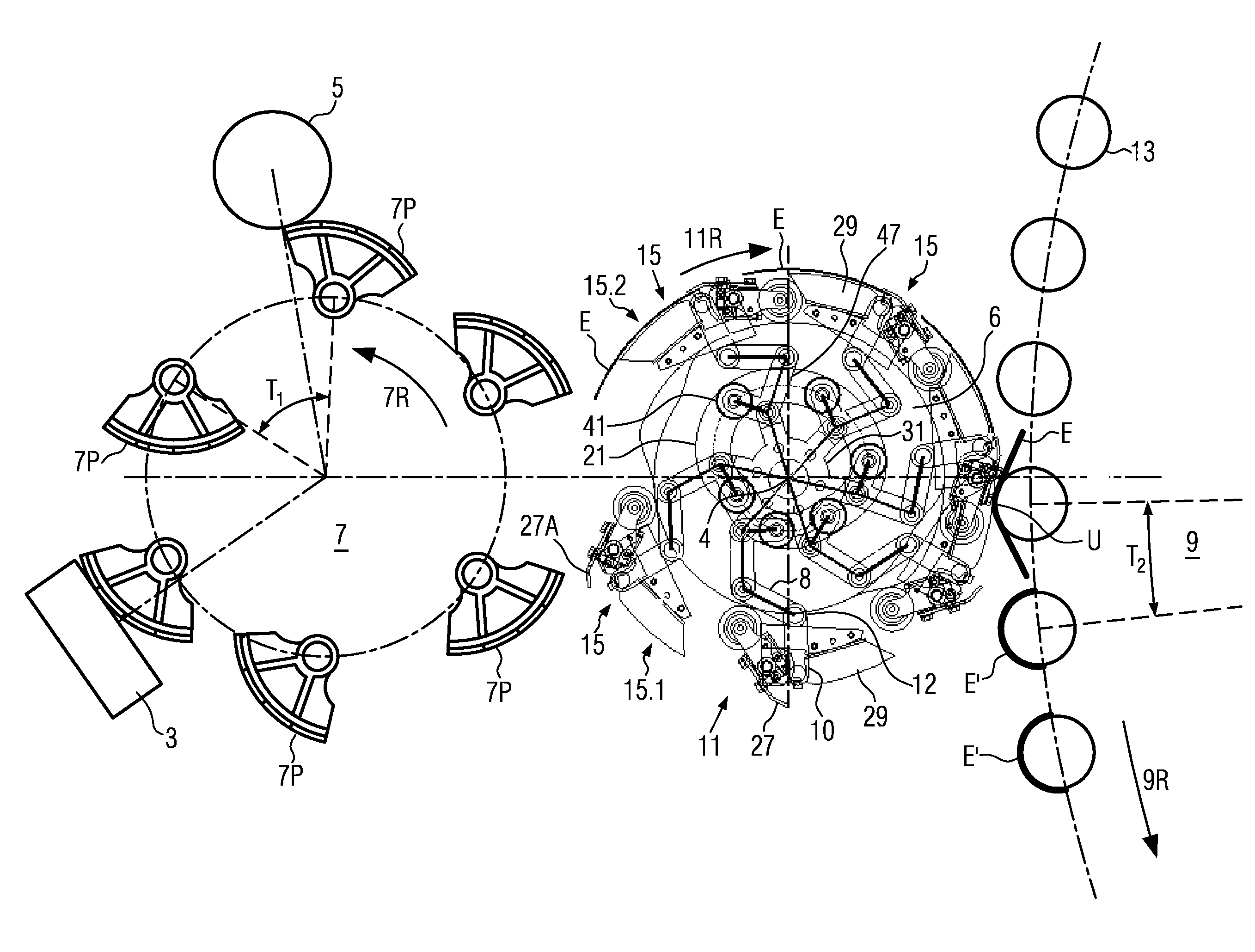
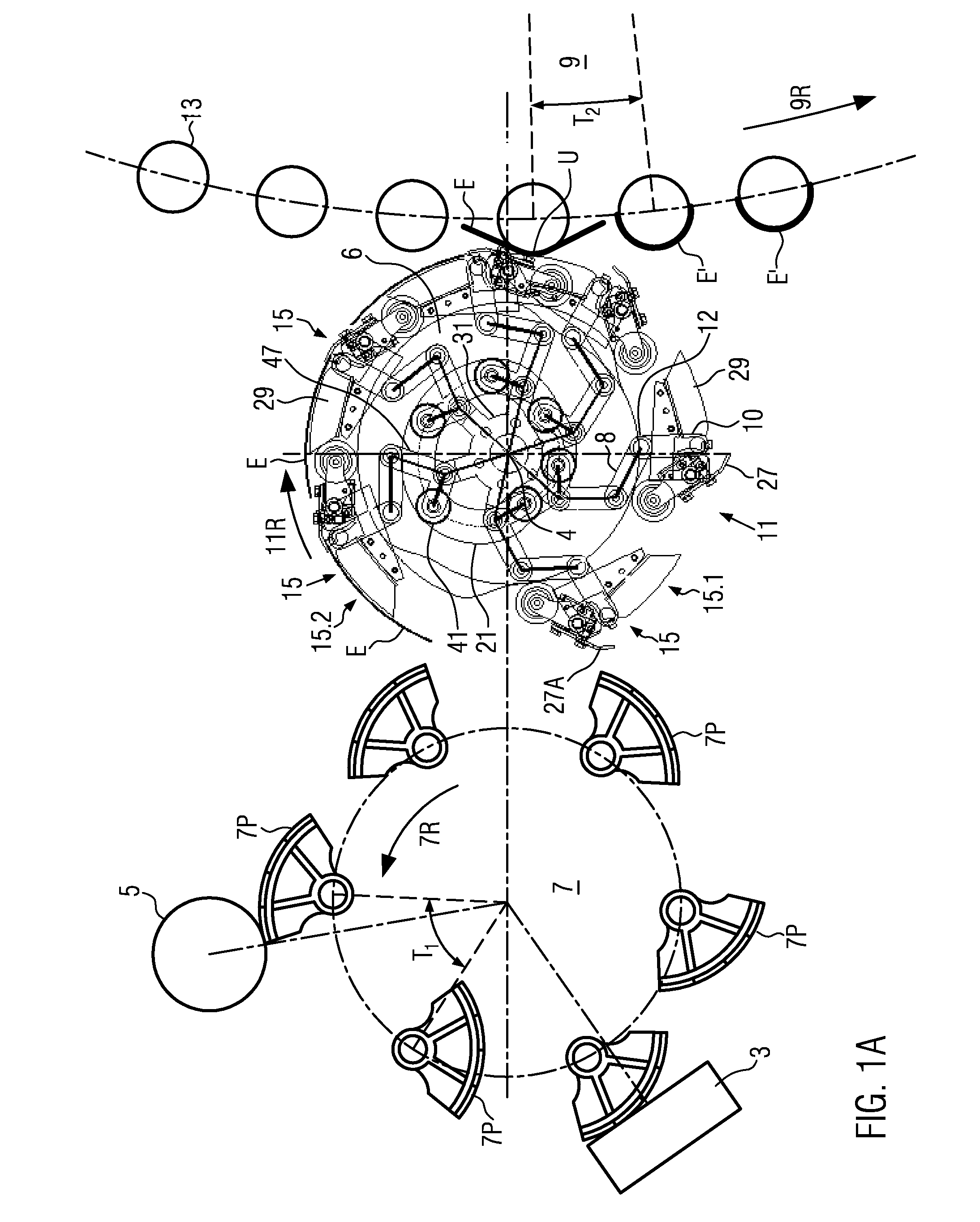
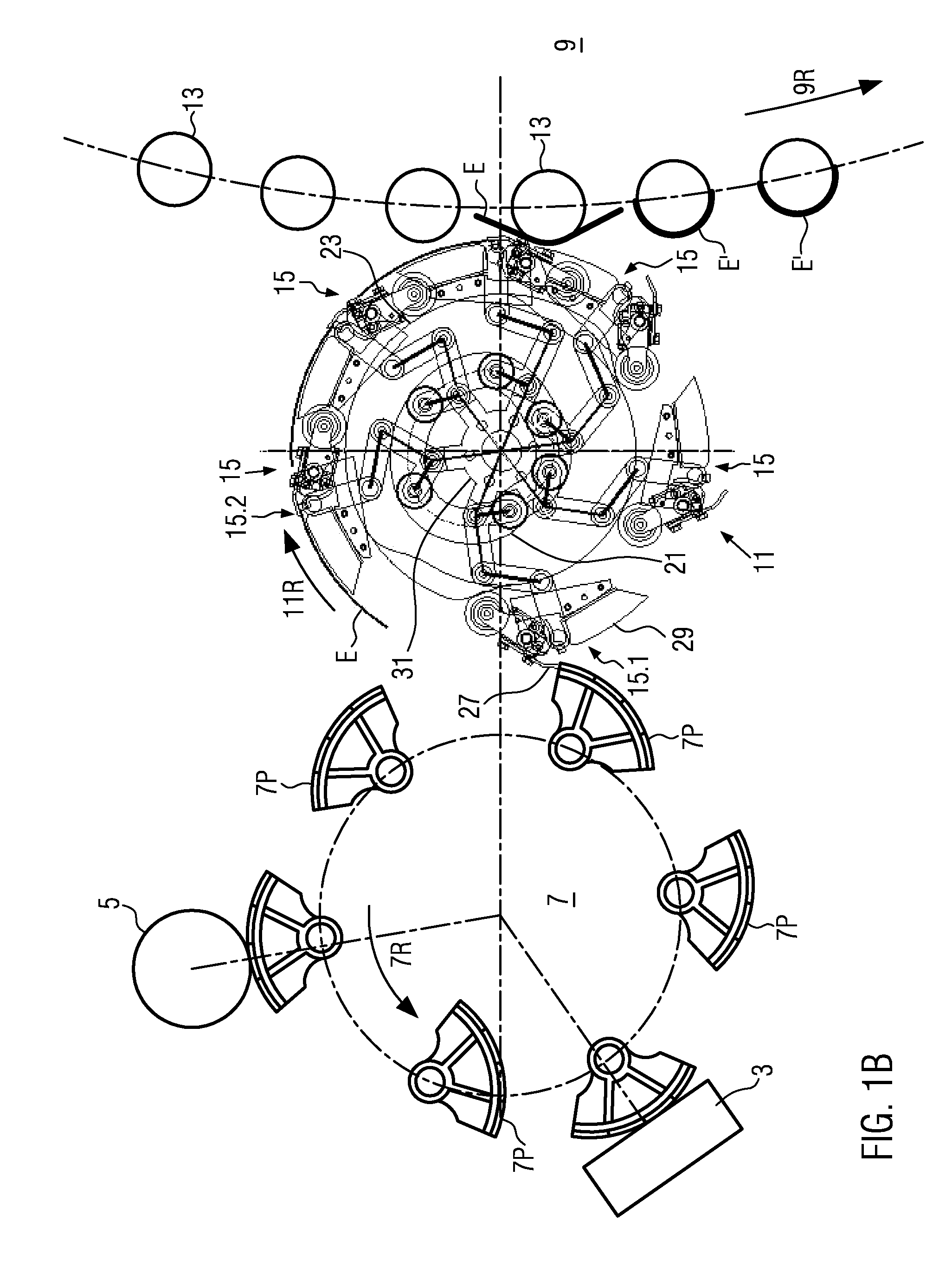
[0038]FIGS. 1A-1D show different stages of a reduction within one rotation at a device 11 for transferring labels E, E′ according to an embodiment of the present disclosure. FIGS. 1A-1D show a feeder or pallet unit with a pallet rotor 7 and pallets 7P which are mounted essentially uniformly on the periphery of the pallet rotor 7. The pallets 7P are movably suspended at axles which are essentially parallel to the axle of the pallet rotor. The distance of the central points of the axles from two adjacent pallets 7P defines a first pitch T1. Furthermore, a glue station or gum roll 5 known in glue labeling, and a label reservoir 3 are shown in FIGS. 1A-1D. The pallets 7P which are essentially directed outwards and have a bent facing to the outside are guided past the gum roll 5 and there take up glue or another adhesive suited for labels. In the process, the pallet rotor 7 rotates, for example, into the direction indicated by the arrow with reference numeral 7R, that means here counter ...


PUM

PropertyMeasurementUnit
relative speedaaaaaaaaaa
constant rotationaaaaaaaaaa
lengthsaaaaaaaaaa

Abstract

A device for transferring labels in a labeling machine with at least two retaining elements for holding labels, with the retaining elements being mounted offset in the circumferential direction around a gripper cylinder axle, and a mechanical control means configured to change the relative speed between the retaining elements in the circumferential direction of the gripper cylinder.

Description

CROSS-REFERENCE TO RELATED APPLICATION[0001]The present application claims the benefit of priority of German Application No. 102011088096.8, filed Dec. 9, 2011. The entire text of the priority application is incorporated herein by reference in its entirety.FIELD OF THE DISCLOSURE[0002]The disclosure relates to a device for transferring labels in a labeling machine and to a corresponding method.BACKGROUND[0003]In the labeling of containers, in particular in cold glue labeling, there are many variants for the combination of label feeders, i.e. pallet units, bottle carousels with the containers to be labeled, and the transfer units used in-between, i.e. gripper cylinders. In particular, the pitch of the bottle carousel, i.e. how many bottles or containers per angular element are to be labeled on the carousel, the pitch of the feeder, i.e. how many transfer positions and thus pallets per angular element are provided, have an influence on the pitch of the transfer unit, i.e. the gripper ...

Claims


Application Information

Patent Timeline
Patent Type & Authority Patents(United States)
IPC IPC(8): B32B41/00B65C3/24B65C9/16B65C3/20
CPCB65C3/20B65C3/24B65C9/16Y10T156/17Y10T156/1754Y10T156/1773Y10T156/1011B65C9/08Y10T156/178Y10T156/10
Inventor PEUTL, AUGUSTHELMBERGER, PAULDOMEIER, BERNHARD
Owner KRONES AG
Why Eureka
Try Eureka