Dual-cylinder rotation type compressor and refrigerator with same
A technology of rotary compressor and compression mechanism, applied in the field of double-cylinder rotary compressor and refrigeration device, can solve the problems of no advantage and no practical application, and achieve noise reduction, sliding loss reduction, and eccentric shaft failure reduction. small effect
- Summary
- Abstract
- Description
- Claims
- Application Information
AI Technical Summary
Problems solved by technology
Method used
Image
Examples
Embodiment 1
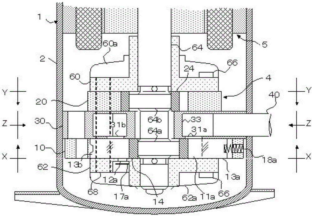
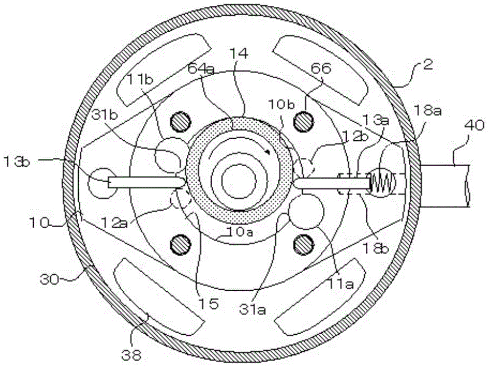
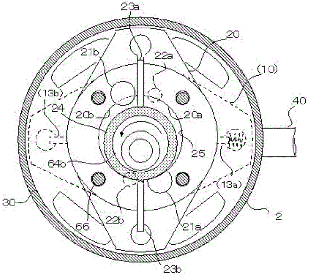
[0053] figure 1 It is a sectional view of the compression mechanism 4 fixed in the housing 2 . figure 2 for figure 1 XX-X section. image 3 for figure 1 The Y-Y section. Figure 4 for figure 1 The Z-Z section.
[0054] exist figure 1 Among them, the motor 5 and the compression mechanism 4 are fixed in the inner diameter of the housing 2 . The compression mechanism 4 has a cylinder A10 and a cylinder B20, and an intermediate partition plate 30 is provided therebetween. The above-mentioned two cylinders are respectively fixed on the intermediate partition 30 together with the auxiliary bearing 62 and the main bearing 60 by four assembly screws 66 . The eccentric shaft 64 is slidably supported by the main bearing 60 and the sub bearing 62 .
[0055] figure 2 The cylindrical compression chamber A15 provided at the center of the illustrated cylinder A10 is divided into a compression chamber 10a and a compression chamber 10b2 by the piston 14 and two sliding plates 13a a...
Embodiment 2
[0074] Embodiment 2 is related to the technology of adding an intake valve to increase the cooling capacity. Figure 6 and Figure 7 The middle and low-pressure gas suction holes serving as the compression chambers 10a are provided with tapered grooves 19a in the two compression chambers. The tapered groove 19a is a groove inclined toward the compression chamber 10a, and the low-pressure hole 31a of the intermediate partition 30 opens to the tapered groove 19a. In Embodiment 2, tapered grooves 19a are provided in the four compression chambers of cylinder A10 and cylinder B20.
[0075] Figure 8 The central bulkhead 30 shown represents the interface with the cylinder A10. The low-pressure hole 31a and the low-pressure hole 31b opened to the contact surface are fixed with the suction valve 35 by the flat screw 45 on the opening surface. Similarly, an intake valve 35 is also fixed to the low-pressure hole 32 a and the low-pressure hole 32 b provided on the contact surface wit...
PUM
 Abstract
Description
Claims
Application Information
 - R&D
- Intellectual Property
- Life Sciences
- Materials
- Tech Scout
- Unparalleled Data Quality
- Higher Quality Content
- 60% Fewer Hallucinations
Browse by: Latest US Patents, China's latest patents, Technical Efficacy Thesaurus, Application Domain, Technology Topic, Popular Technical Reports.
© 2025 PatSnap. All rights reserved.Legal|Privacy policy|Modern Slavery Act Transparency Statement|Sitemap|About US| Contact US: help@patsnap.com


