Biomass pellet burner heating pipe connection device

A biomass particle, connecting device technology, applied in the direction of pipes/pipe joints/pipes, pipes, pipe elements, etc., can solve the problems of large flow resistance of heat fluid, low heat exchange efficiency of heat fluid, waste of energy, etc. The effect of reducing output resistance, improving energy utilization efficiency, and high heat exchange efficiency

Active Publication Date: 2018-10-23
DONGGUAN HUARONG COATING EQUIP
View PDF11 Cites 0 Cited by
  • Summary
  • Abstract
  • Description
  • Claims
  • Application Information

AI Technical Summary

Problems solved by technology

When the heating pipe is in actual use, when the heat fluid output from the biomass pellet burner flows through the elbow, at this time, the flow resistance of the heat fluid inside the elbow is large, which is not conducive to the transportation of heat fluid in the heat pipe , causing the heat exchange efficiency of the thermal fluid to be low, resulting in a waste of energy
[0003] Moreover, when performing pipeline maintenance, the heating pipeline using traditional bent pipes is not convenient for maintenance operations, which greatly increases the difficulty of maintenance and reduces the efficiency of manual maintenance operations
[0004] To sum up, the industry needs a heating pipe connection device for biomass pellet burners, which is aimed at the laying and installation of heating pipes, and is used to solve the problem of large flow resistance of heat fluid at the turning point of heat pipe and heat exchange of heat fluid. The efficiency is not high, resulting in the problem of energy waste. At the same time, it is used to solve the problem of inconvenient maintenance of heating pipes

Method used


Image

  • Biomass pellet burner heating pipe connection device
  • Biomass pellet burner heating pipe connection device

Examples


Embodiment Construction

[0017] Specific embodiments of the present invention will be described below in conjunction with the accompanying drawings. It should be understood that the specific implementations described here are only used to illustrate and explain the description, and are not intended to limit the present invention.

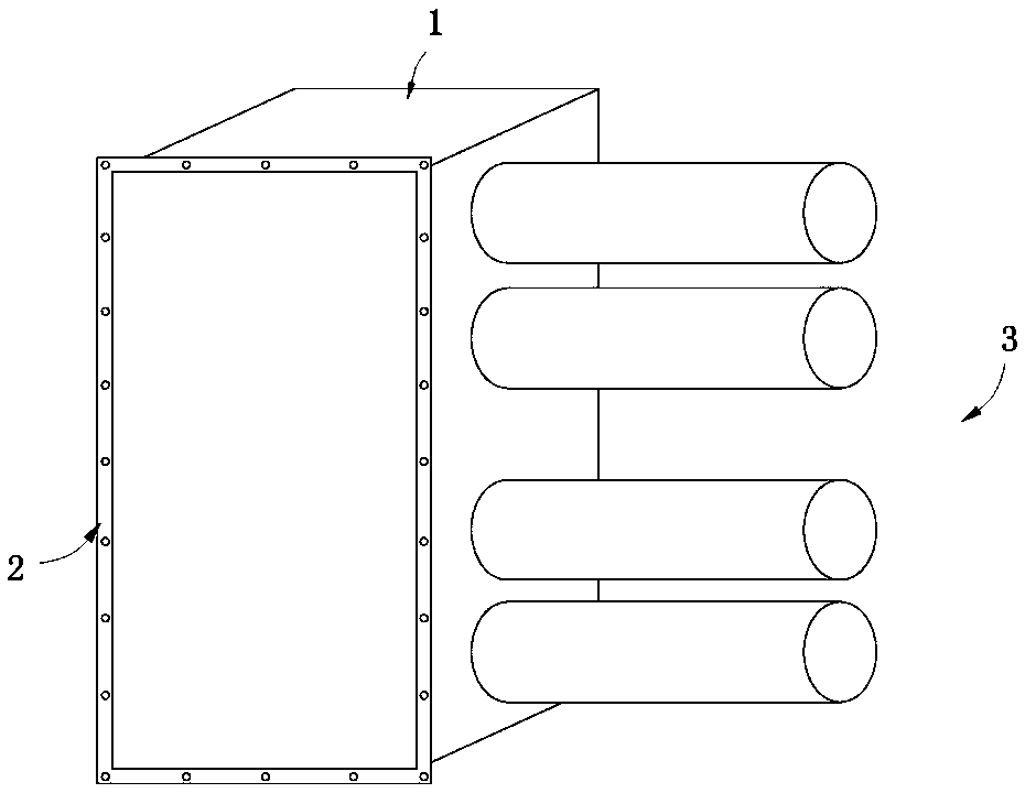
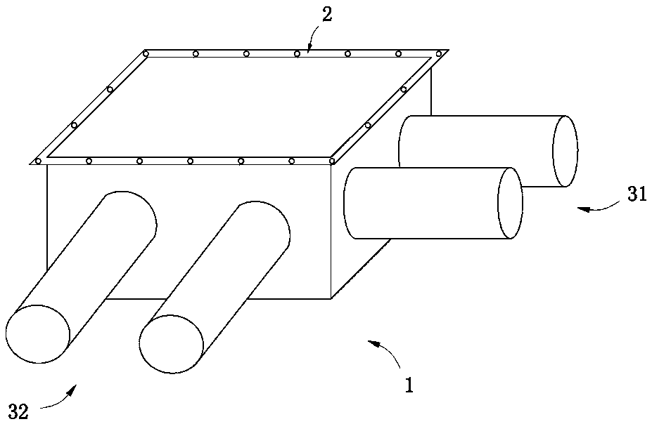
[0018] figure 1 A schematic structural view of a heating pipe connection device for a biomass pellet burner according to an embodiment of the present invention is shown. Wherein, when the heating pipes are connected in a 180-degree turn, the connecting ends of the multiple heating pipes are connected to the interface of the connecting part provided on one side of the box body, and the multiple heating pipes are arranged in parallel.

[0019] Such as figure 1 As shown, the connecting device of the heating pipe of the biomass pellet burner includes: a box body 1 provided with a heat fluid containing space, an inspection cover 2 arranged on one side of the box body 1 for sea...


PUM


Abstract

The invention discloses a heating pipeline connecting device of a biomass particle burner. The heating pipeline connecting device of the biomass particle burner comprises a box body, an access cover arranged at one side of the box body, and a connecting part arranged on at least one lateral surface of the box body, the box body is separated from the access cover, and a port for connecting at least two heating pipes is formed in the connecting part. The heating pipeline connecting device of the biomass particle burner is smart in design and reasonable in structure. The heating pipeline connecting device of the biomass particle burner is used for replacing a traditional bend to connect at the corner of the heating pipe, because a hot fluid holding space is large enough, the hot fluid input and output resistance is greatly reduced, by means of the hot fluid conveying, the heat exchange efficiency is high, and the energy use efficiency is improved. The access cover facilitates maintaining when carrying out current maintenance and repair on the heating pipeline, the working efficiency is high, the overall equipment has a good running state, and the service life of the equipment is prolonged. The heating pipeline connecting device of the biomass particle burner is further suitable for connecting heating pipelines of different types of heat supply equipment; the heating pipeline connecting device of the biomass particle burner is good for mounting and maintaining the heating pipelines and convenient for manual operation.

Description

technical field [0001] The invention relates to the technical field of pipe connection, in particular to a heating pipe connection device for a biomass pellet burner. Background technique [0002] At present, the laying and installation of heating pipes of biomass pellet burners mostly require elbows for connection. Pipe, laying and installing heating pipes. When the heating pipe is in actual use, when the heat fluid output from the biomass pellet burner flows through the elbow, at this time, the flow resistance of the heat fluid inside the elbow is large, which is not conducive to the transportation of heat fluid in the heat pipe , causing the heat exchange efficiency of the thermal fluid to be low, resulting in a waste of energy. [0003] Moreover, when performing pipeline maintenance, it is inconvenient to maintain the heating pipeline using traditional bent pipes, which greatly increases the difficulty of maintenance and reduces the efficiency of manual maintenance ope...

Claims


Application Information

Patent Timeline
Patent Type & Authority Patents(China)
IPC IPC(8): F16L41/03F16L45/00
CPCF16L41/03F16L45/00
Inventor 张文文
Owner DONGGUAN HUARONG COATING EQUIP
Why Eureka
Try Eureka