Extractor hood

A range hood and flue gas technology, which is applied in the direction of removing oil fume, household heating, lighting and heating equipment, etc. It can solve the problems of large flow loss and increased wind resistance

Active Publication Date: 2015-04-29
BSH ELECTRICAL APPLIANCES JIANGSU
View PDF6 Cites 8 Cited by
  • Summary
  • Abstract
  • Description
  • Claims
  • Application Information

AI Technical Summary

Problems solved by technology

For some range hoods, the oil fume is sucked from the gap between the smoke collecting hood and the outer edge of the smoke deflector, but most of the existing sm

Method used


Image

  • Extractor hood
  • Extractor hood
  • Extractor hood

Examples


Embodiment Construction

[0036] In order to have a further understanding of the purpose, structure, features, and functions of the present invention, the following detailed descriptions are provided in conjunction with the embodiments.

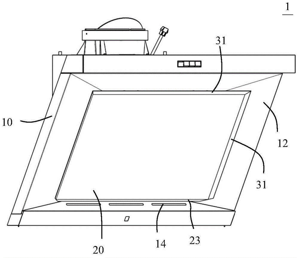
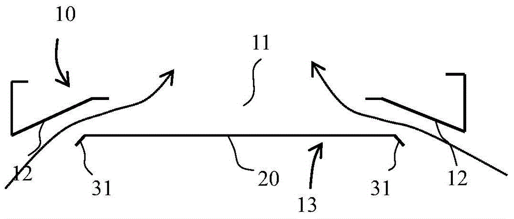
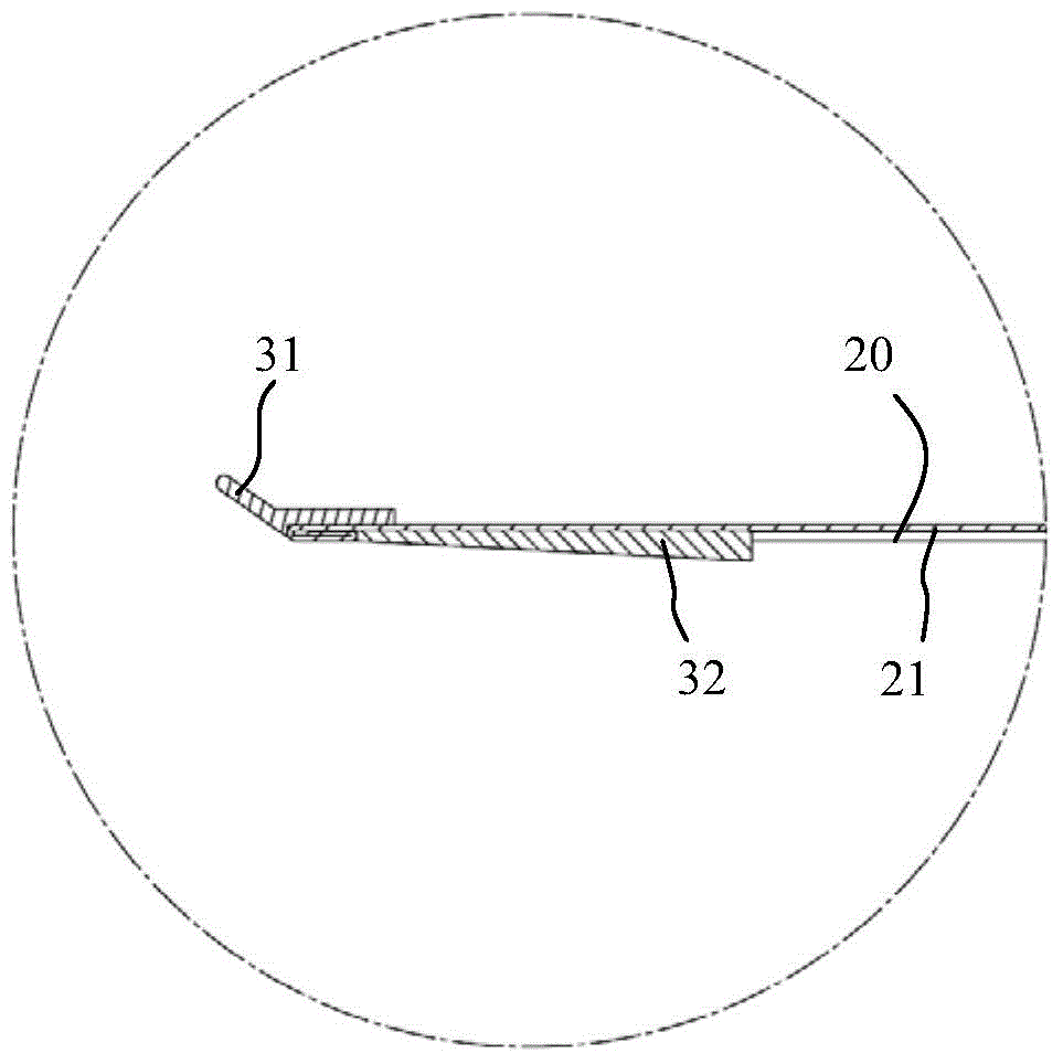
[0037] The present invention provides a range hood. Although a side-suction range hood is used as an example for illustration in the specification and drawings, the present invention is not limited thereto. like figure 1 , figure 2 as shown, figure 1 It is a perspective view of a range hood according to an embodiment of the present invention, figure 2 It is a schematic diagram of a smoke guide plate and a smoke collection hood according to an embodiment of the present invention. The range hood 1 includes a smoke collecting hood 10 and a smoke guide plate 20. There is a gap between the smoke collecting hood 10 and the outer edge of the smoke guide plate 20 for smoke to pass through. Resistance deflector.

[0038] like figure 1 As shown, the range hood 1 of this...


PUM


Abstract

The invention provides an extractor hood. The extractor hood comprises an exhaust fume collecting hood and a smoke deflector, wherein a gap allowing smoke to pass through is formed between the periphery of the exhaust fume collecting hood and the periphery of the smoke deflector; and a diversion part capable of reducing the air inlet resistance is arranged on the edge of the smoke deflector. According to the extractor hood, the air inlet resistance at the edge of the smoke deflector is reduced due to the arrangement of the diversion part, and the smoke can be sucked in smoothly.

Description

【Technical field】 [0001] The invention relates to a kitchen household appliance, in particular to a range hood. 【Background technique】 [0002] The range hood, also known as the range hood, is a kitchen appliance that purifies the kitchen environment. It can quickly suck away the waste burned by the stove and the harmful oil fume generated during the cooking process. For some range hoods, the oil fume is sucked from the gap between the smoke collecting hood and the outer edge of the smoke deflector, but most of the existing smoke deflectors are simple flat structures, and no optimized design is made on the smoke deflector. This will cause greater flow loss and increase wind resistance. [0003] References to prior art herein are not intended to be an admission that such prior art was known to those of ordinary skill in the art to which the present invention pertains prior to the filing date of this application, unless supported by sufficient evidence. 【Content of inventio...

Claims


Application Information

Patent Timeline
IPC IPC(8): F24C15/20
CPCF24C15/20
Inventor 杨磊唐俊杰夏兆阳邹伟
Owner BSH ELECTRICAL APPLIANCES JIANGSU
Why Eureka
Try Eureka