Center alignment device for coupler

A coupling and axial technology, applied in the field of measurement, can solve the problems of poor reliability of the motor shaft center, easy deformation of the cantilever, limited span, etc., and achieve the effects of accurate and fast installation, flexible alignment device, and improved efficiency.

Active Publication Date: 2015-04-29
GUANGDONG TOPKEY POWER TECHN DEV
View PDF6 Cites 5 Cited by
  • Summary
  • Abstract
  • Description
  • Claims
  • Application Information

AI Technical Summary

Problems solved by technology

[0002] At present, for the center alignment of the motor with a short shaft, the conventional magnetic base is mostly used. The magnetic base is used to fix the motor shaft. The dial indicator is connected to the magnetic base through a cantilever, and the magnetic base is used for alignment. The disadvantage is that the cantilever is not long enough and the span is limited. The cantilever is generally made of two connecting rod hinges, which makes the cantilever easy to deform. For center alignment, the longer the arm, the easier the deformation and the greater the center error
The installation and maintenance of the motor shaft requires the use of multiple magnetic bases, and the installation one by one will have asymmetrical errors that will affect the alignment efficiency. The final installation and adjustment of the dial indicator is inefficient, and the reliability of the adjustment process of the motor shaft center is poor.

Method used


Image

  • Center alignment device for coupler
  • Center alignment device for coupler
  • Center alignment device for coupler

Examples


Embodiment Construction

[0028] The specific implementation manners of the present invention will be further described in detail below in conjunction with the accompanying drawings and embodiments. The following examples are used to illustrate the present invention, but are not intended to limit the scope of the present invention.

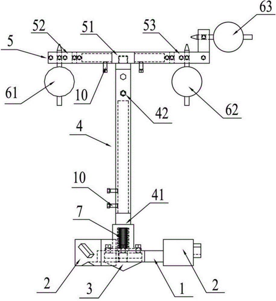
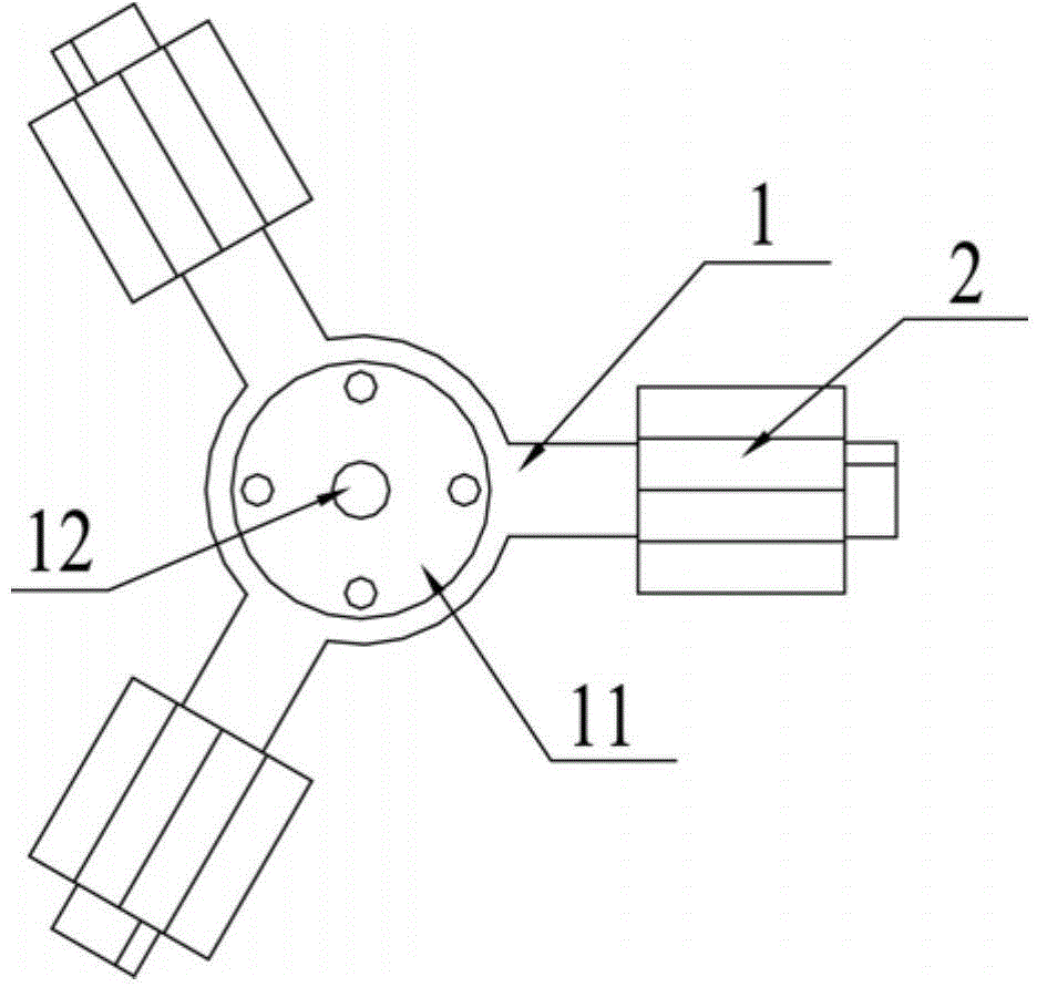
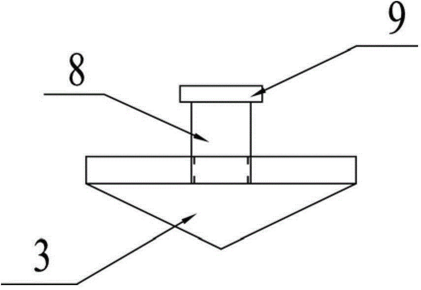
[0029] Such as figure 1 As shown, a coupling center alignment device according to a preferred embodiment of the present invention includes a fixed base 1, a cone 3, an axial adjustment rod 4, a radial adjustment rod 5 and a dial indicator, and the axial adjustment rod 4 One end of the fixed base 1 is connected to the fixed base 1, the other end of the axial adjustment rod 4 is connected to the center of the radial adjustment rod 5, the outer periphery of the fixed base 1 is provided with a magnetic base 2, and the bottom center of the fixed base 1 is provided with a The cone 3 in the center of the center hole, the cone 3 is coaxially arranged with the axial adjustment rod...


PUM


Abstract

The invention relates to the technical field of measurement, and discloses a center alignment device for a coupler. The center alignment device comprises a fixing base, a conical body, an axial adjusting rod, a radial adjusting rod and dial indicators. One end of the axial adjusting rod is connected with the fixing base, the other end of the axial adjusting rod is connected with the center of the radial adjusting rod, a magnetic base used for being attracted to and fixed to a motor shaft is arranged on the periphery of the fixing base, the conical body is disposed in the center of the bottom of the fixing base, the conical body and the axial adjusting rod are coaxially arranged and used for being aligned to a center hole of the motor shaft, and the dial indicators are installed at the two ends of the radial adjusting rod respectively. The conical body is designed in the center of the bottom of the fixing base so that the center hole of the motor shaft can be quickly found and aligned, and the magnetic base is attracted to and fixed to the motor shaft so that installation can be more precise and quicker. Besides, the conical body can installed in the bottom of the fixing base in a telescopic rod, center alignment is convenient to achieve, and machining difficulty is lowered.

Description

technical field [0001] The invention relates to the technical field of measurement, in particular to a coupling center alignment device. Background technique [0002] At present, for the center alignment of the motor with a short shaft, the conventional magnetic base is mostly used. The magnetic base is used to fix the motor shaft. The dial indicator is connected to the magnetic base through a cantilever, and the magnetic base is used for alignment. The disadvantage is that the cantilever is not long enough and the span is limited. The cantilever is generally made of two connecting rod hinges, which makes the cantilever easy to deform. For center alignment, the longer the arm, the easier the deformation and the greater the center error. The installation and maintenance of the motor shaft requires the use of multiple magnetic gauges, and the installation one by one will have asymmetrical errors that will affect the alignment efficiency. The final installation and adjustment o...

Claims


Application Information

Patent Timeline
Patent Type & Authority Applications(China)
IPC IPC(8): G01B5/00G01B5/252
Inventor 庄秀忠谭光雄吴伟彪郑家钺苏武
Owner GUANGDONG TOPKEY POWER TECHN DEV
Why Eureka
Try Eureka