Sensor device and method

A sensor device, magnetoresistive sensor technology, applied in the direction of measurement device, electromagnetic device manufacturing/processing, instrument, etc., can solve the problems of inability to identify, increase in XMR sensor price and safety features, production workload and high cost, etc.

Active Publication Date: 2015-04-29
INFINEON TECH AG
View PDF7 Cites 20 Cited by
  • Summary
  • Abstract
  • Description
  • Claims
  • Application Information

AI Technical Summary

Problems solved by technology

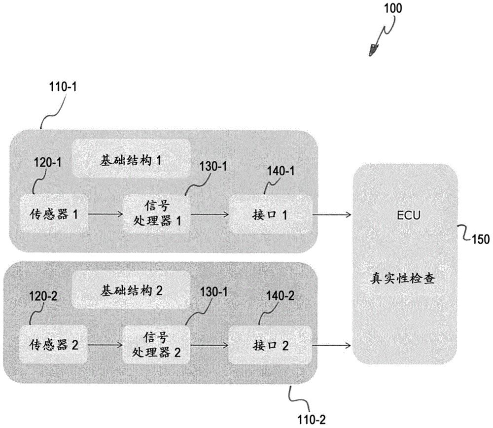
Traditional solutions include redundant concepts featuring two independently manufactured sensors, which are expensive in terms of production effort and cost
Traditional solutions also include security algorithms with only limited performance, which cause unrecognizable errors
As a result, the price of XMR sensors increases significantly along with their functional safety features

Method used


Image

  • Sensor device and method
  • Sensor device and method
  • Sensor device and method

Examples


Embodiment Construction

[0035] Example embodiments will now be described more fully with reference to the accompanying drawings, in which some example embodiments are illustrated. In the drawings, the thickness of lines, layers and / or regions may be exaggerated for clarity.

[0036] Therefore, while the exemplary embodiments are capable of various modifications and alternative forms, embodiments thereof are shown by way of example in the drawings and described in detail herein. It should be understood, however, that there is no intention to limit example embodiments to the particular forms disclosed, but on the contrary, example embodiments are to cover all modifications, equivalents, and alternatives falling within the scope of the invention. Throughout the description of the drawings, the same reference numerals refer to the same or similar elements.

[0037] It will be understood that when an element is referred to as being "connected" or "coupled" to another element, it can be directly connected...


PUM


Abstract

Embodiments relate to a sensor device including a layer stack 600, the layer stack 600 including at least ferromagnetic and non-magnetic layers formed on a common substrate 620. The sensor device 600 further includes at least a first magneto-resistive sensor element 711 provided by a first section 611 of the layer stack 600. The first magneto-resistive sensor element 711 herein is configured to generate a first signal. The sensor device 600 also includes a second magneto-resistive sensor element 712 provided by a second section 612 of the layer stack 610. The second magneto-resistive sensor element 712 herein is configured to generate a second signal for verifying the first signal.

Description

technical field [0001] Embodiments relate to sensor devices, or more particularly to sensor devices comprising magnetoresistive sensor elements. Background technique [0002] The magnetoresistive effect includes a large number of different physical phenomena, all of which have in common that the resistance of an impedance element can be modified by the behavior of a magnetic field passing through the impedance element. Techniques that exploit the magnetoresistance effect are sometimes referred to as "XMR techniques", where X denotes the diversity of effects that can be addressed here. [0003] One example is the anisotropic magnetoresistance (AMR) effect, which is based on the fact that in a (nano)thin conducting layer the resistance can be changed by changing the angle between an external magnetic field and the direction of current flow within the layer. This effect can be explained by distorting the atomic orbitals due to the spin orientation in the magnetic field and thu...

Claims


Application Information

Patent Timeline
Patent Type & Authority Applications(China)
IPC IPC(8): G01D5/18
CPCG01R33/093H10B61/00H10N59/00G11B5/3909G11B5/3903G11B5/3948G11B5/3961H10N50/01
Inventor J·齐默H·威特施尼格
Owner INFINEON TECH AG
Why Eureka
Try Eureka