Method of tread wear sensor installation in a tire

a technology of wear sensor and tire, which is applied in the field of sensing system, can solve the problems of increasing the complexity of tire formation, difficult and no way for the operator to determine the level of wear

Active Publication Date: 2014-12-11
THE GOODYEAR TIRE & RUBBER CO
View PDF15 Cites 21 Cited by
  • Summary
  • Abstract
  • Description
  • Claims
  • Application Information

AI Technical Summary

Benefits of technology

[0006]According to an aspect of the invention a method of installing a tread wear sensor in a tire includes configuring tread wear indicators to each include a stack of sacrificial resistive sensor elements. The stacks of resistive sensor elements are affixed to respective selected tread elements (lugs) positioned at dispersed axial locations across a tire tread

Problems solved by technology

The practical problem with the colored indicators of the type mentioned is that there is no way for the operator to determine the level of wear until the tire is worn.
When the tire employs the tie-bar type wear indicator, it can be difficu

Method used


Image

  • Method of tread wear sensor installation in a tire
  • Method of tread wear sensor installation in a tire
  • Method of tread wear sensor installation in a tire

Examples


Embodiment Construction

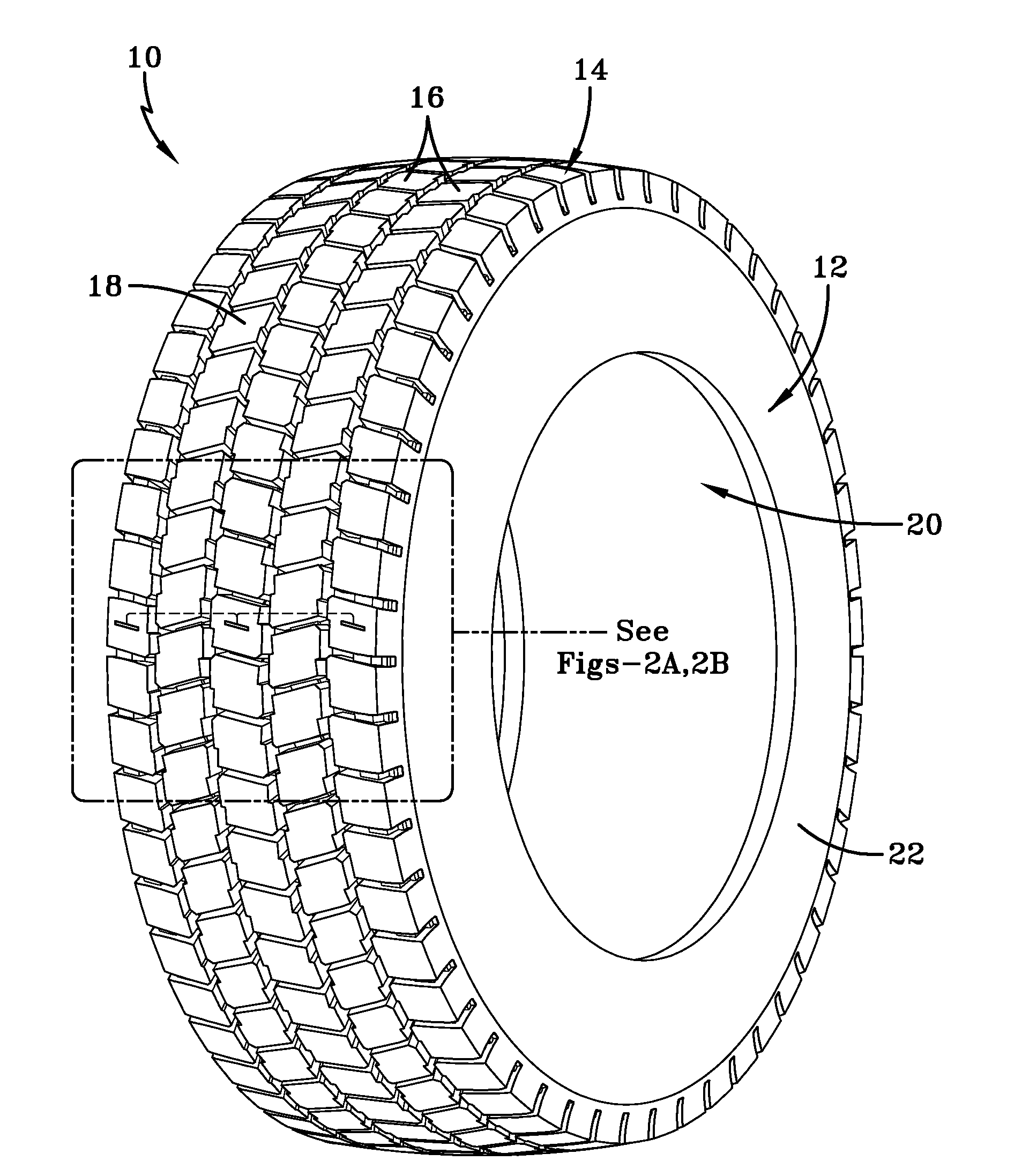
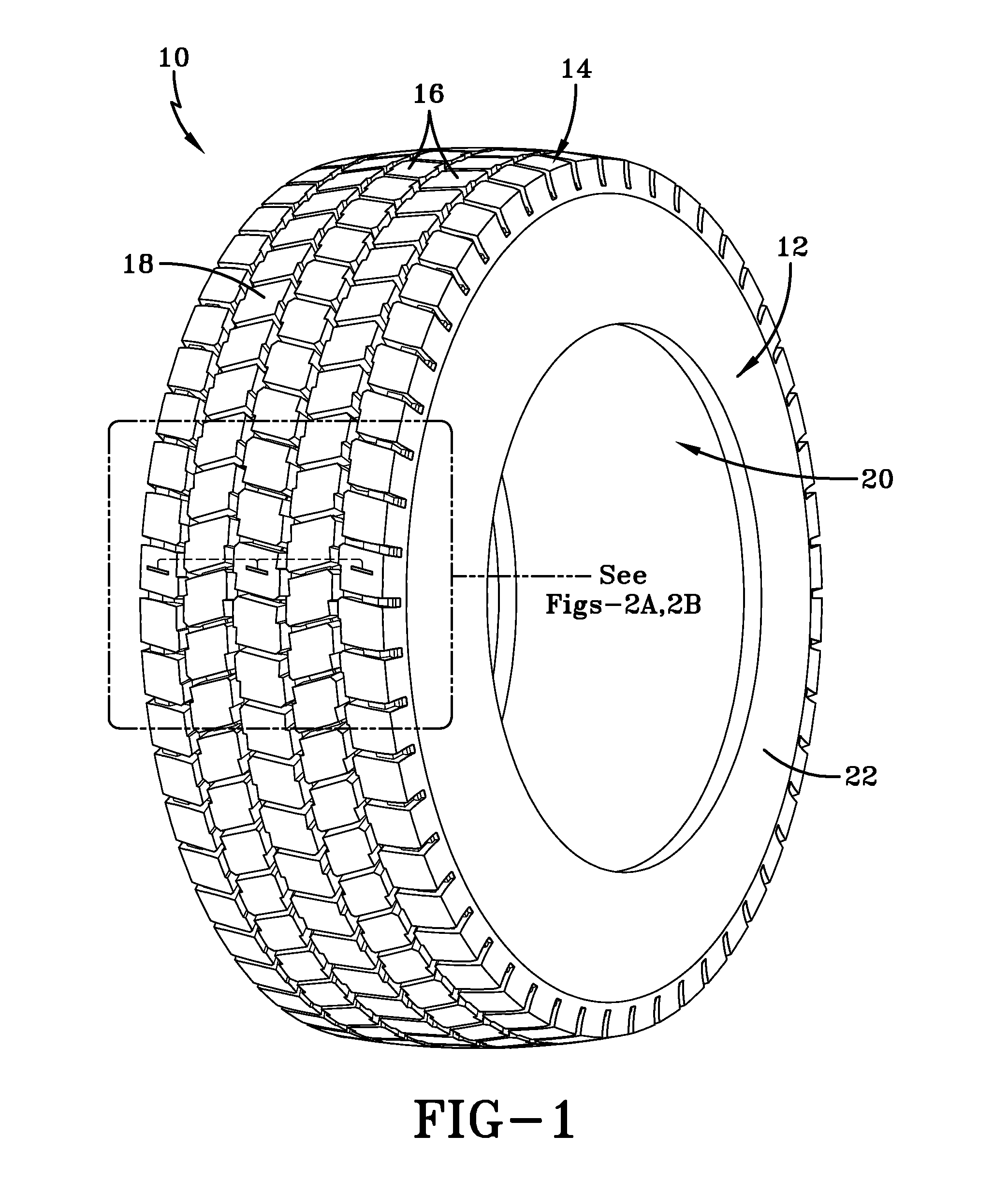
[0040]Referring to FIGS. 1, 2A and 2B, a representative tire assembly 10 is shown including a vehicle tire 12 having a radially outward tread 14 defined into multiple circumferential tread rows 16. Within each of the tread rows 16 is a circumferential array of tread elements 18, also referred to herein as tread lugs or blocks. The tire 12 further includes an internal cavity 20. Pursuant to conventional tire construction, the tire 12 is formed as a tire carcass 22 in a green tire build procedure and subsequently cured into the finished tire product.

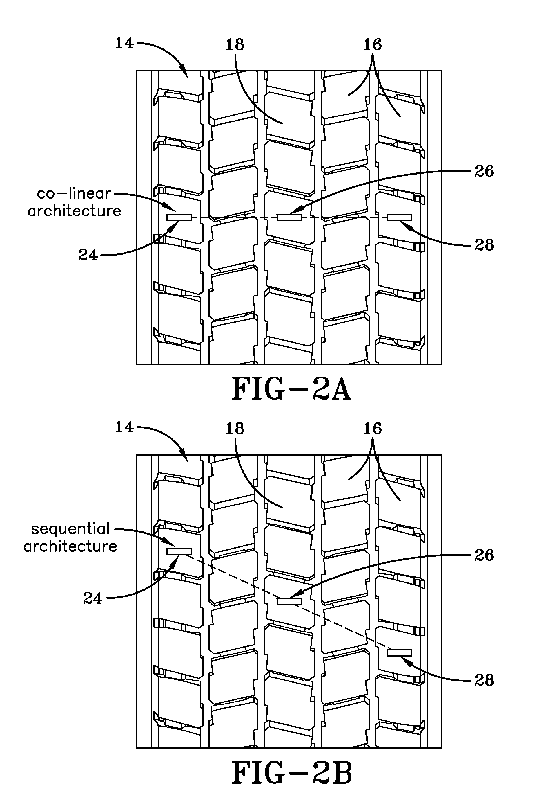
[0041]FIGS. 2A and 2B show enlargement views of the tread region, illustrating the tread rows 16 formed by the spaced apart tread blocks 18. At least one of the tread blocks 18, and preferably multiple tread blocks, are equipped with a resistive sensor 24, also referred herein as a “wear sensor” or “treadwear indicator”. As seen in the sensor configuration of FIG. 2A, the tread lugs 18 equipped with wear sensors 24, 26 and 28 are lugs whic...


PUM


Abstract

A method of installing a tread wear sensor in a tire includes configuring multiple tread wear indicators to each include a stack of sacrificial resistive sensor elements. The stacks of resistive sensor elements are affixed to respective selected tread lugs positioned at dispersed axial locations across a tire tread region. The resistive sensor elements sacrificially abrade and a change in resistance in each stack is measured. Connector assemblies within the tire carcass cavity are positioned radially opposite the selected tread lugs. A needle projection from each of the connector assemblies is inserted radially outward through the tire carrying leads which engage and establish electrical contact with a respective stack of resistive sensor elements.

Description

FIELD OF THE INVENTION[0001]The invention relates generally to a sensing system for real-time monitoring of tire wear over its life time and, more specifically, to a method of installing a wear sensor into a tire.BACKGROUND OF THE INVENTION[0002]The use of tread wear indicators is not new and the use of tread wear indicators is mandated by law in many countries. A variety of such indicators are known. Once such type employs colored indicia below the tread for a visual indicator of wear. Other types use tie-bar type elements in the tread grooves.[0003]The practical problem with the colored indicators of the type mentioned is that there is no way for the operator to determine the level of wear until the tire is worn. When the tire employs the tie-bar type wear indicator, it can be difficult to determine the level of wear.[0004]U.S. Pat. No. 6,523,586 discloses wear indicators for a tire tread wherein, in a series, or predetermined closely located grouping, of related marks, the marks ...

Claims


Application Information

Patent Timeline
IPC IPC(8): G01M17/02
CPCG01M17/02B60C11/243
Inventor ORLEWSKI, PIOTR
Owner THE GOODYEAR TIRE & RUBBER CO
Why Eureka
Try Eureka