

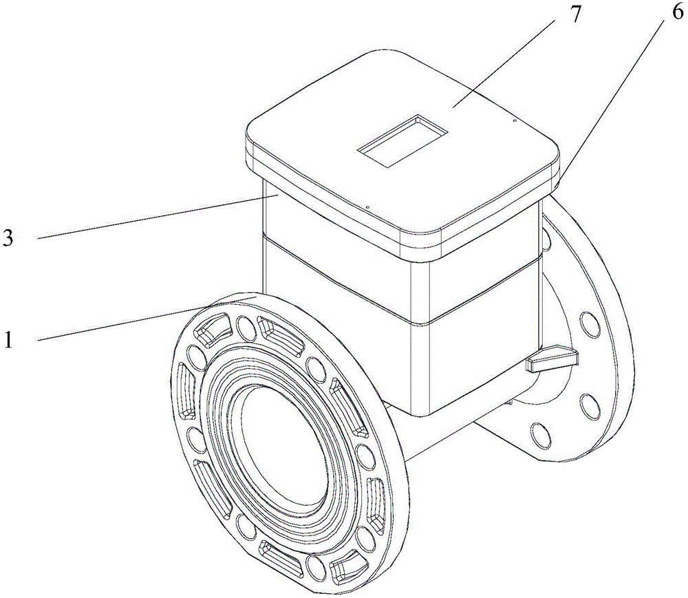
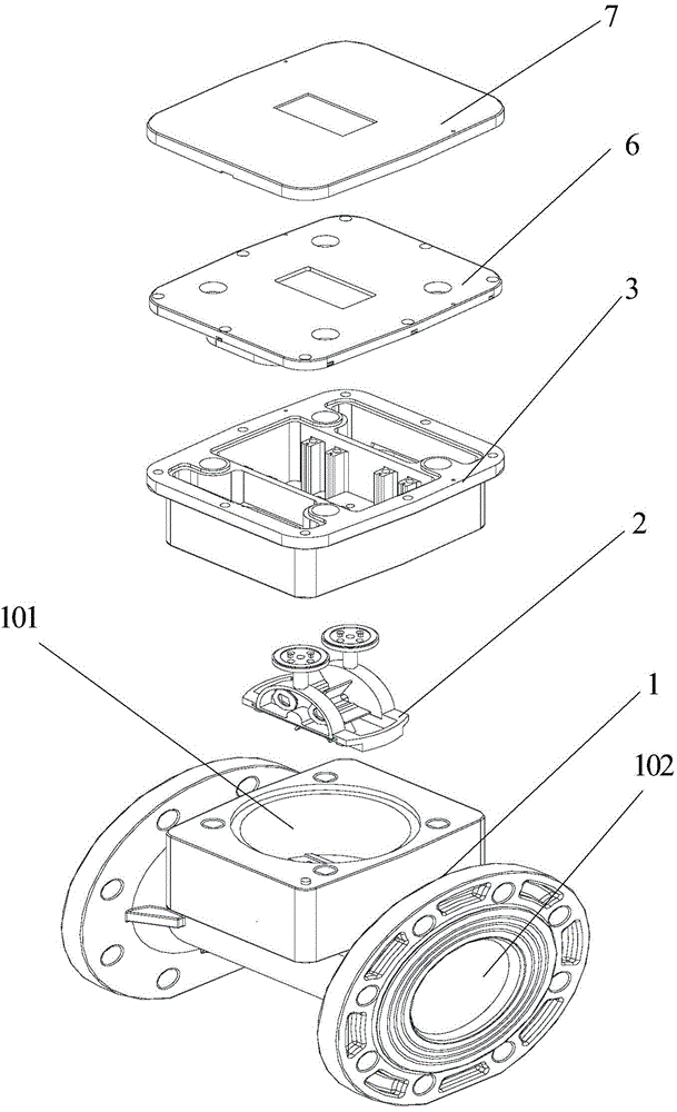
Magneto-electrical flow meter
A flowmeter and magnetoelectric technology, which is applied in the field of magnetoelectric flowmeters, can solve the problems of flowmeters not operating normally, not counting, and inaccurate counting of flowmeters, and achieve the effect of avoiding normal operation
- Summary
- Abstract
- Description
- Claims
- Application Information
AI Technical Summary
Problems solved by technology
Method used
Image

Examples
Embodiment Construction
[0032] In order to enable those skilled in the art to better understand the technical solutions of the present invention, the present invention will be further described in detail below in conjunction with the accompanying drawings and specific embodiments.
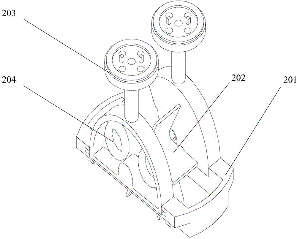
[0033] According to Faraday's law of electromagnetic induction, the present invention utilizes the principle that a conductor coil produces an induced electromotive force in a changing magnetic field to develop and design, the formula is as follows: E=n*ΔΦ / Δt, Faraday's law of electromagnetic induction, E: induced electromotive force (V), n: The number of turns of the induction coil, ΔΦ / Δt is the rate of change of the magnetic flux, and the water flow is used to drive the liquid wheel to rotate. The magnet is fixed on the liquid wheel, and the coil is fixed on one side of the liquid wheel. When rotating, the magnet follows the liquid wheel to rotate, resulting in a change in the magnetic field , the induction coil generate...
PUM
 Abstract
Description
Claims
Application Information