Tray device, assembly line system and material supplementing method
A pallet and equipment technology, applied in the field of assembly line automation of mechanical standard parts, can solve the problems of uncountable standard parts, inconvenient real-time management, resource waste and assembly efficiency, etc., and achieve the effects of real-time monitoring, convenient management, and improved assembly efficiency
- Summary
- Abstract
- Description
- Claims
- Application Information
AI Technical Summary
Problems solved by technology
Method used
Image
Examples
Embodiment 1
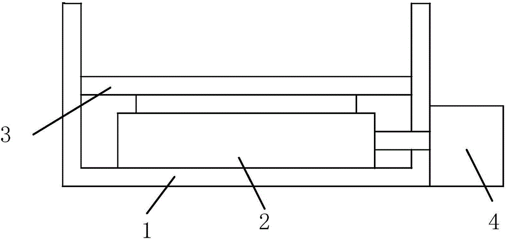
[0026] figure 1 It is a schematic structural diagram of the tray device provided in this embodiment, which includes: a tray 1, a weight sensor 2, a support plate 3, a data acquisition interface and an MCU microprocessor unit 4, wherein:
[0027] The weight sensor 2 is arranged in the tray 1, and the bottom is in contact with the inner surface of the tray 1;
[0028] The support plate 3 is arranged above the weight sensor 2 and is in contact with the weight sensor 2;
[0029] The MCU microprocessor unit 4 is connected with the weight sensor 2 through the data acquisition interface, and is used to read the weight data of the support plate 3 collected by the weight sensor and all standard parts placed on the support plate 3, and generate according to the weight data Standard parts quantity information, and sent to external equipment. Specifically, the MCU microprocessor unit 4 can be placed in a custom-made cuboid box, and the box is fixedly installed on the outside of the tray...
Embodiment 2
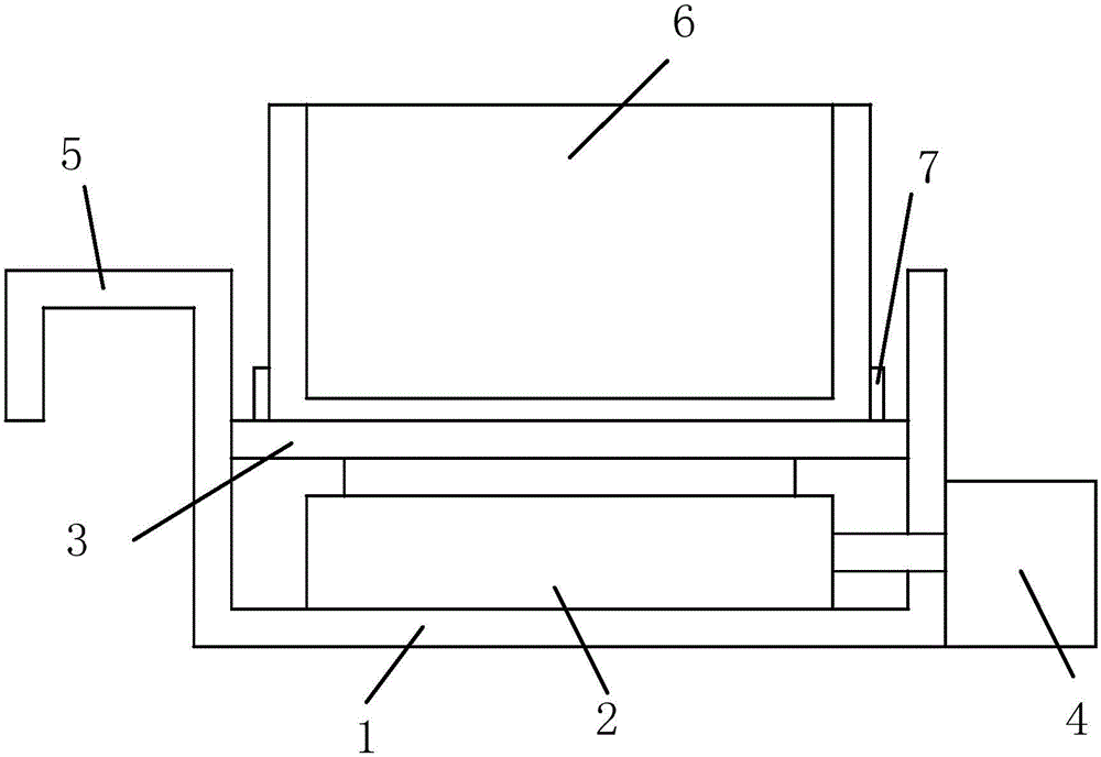
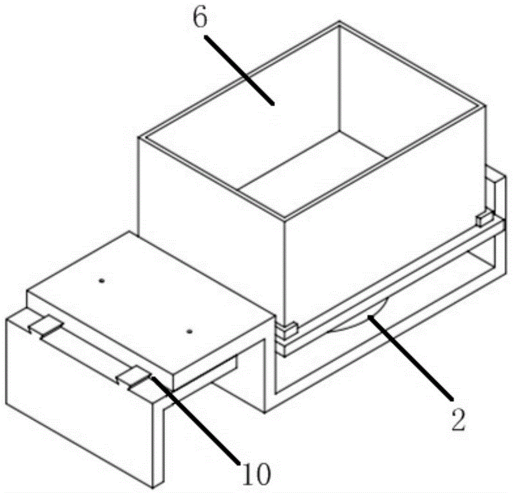
[0037] figure 2 It is a schematic structural diagram of the tray device provided in this embodiment, image 3 with Figure 4 is a schematic perspective view of the tray device provided in this embodiment, Figure 5 It is the three views of the pallet device provided in this embodiment, in which 5a is the main view, 5b is the left view, and 5c is the top view. Such as Figure 2 to Figure 5 As shown, the pallet device includes: pallet 1, weight sensor 2, support plate 3, data acquisition interface, MCU microprocessor unit 4, hook 5 and material box 6, wherein:
[0038] The hook 5 is connected to the tray 1, and is used to hang the tray 1 on the conveyor belt, so that the tray 1 can be better fixed on the conveyor belt; further, the hook 5 is a telescopic structure, preferably a telescoping combination of a dovetail groove and a positioning pin. The structure 10 enables the pallet equipment to be adapted to conveyor belts of different widths by adjusting the retractable stru...
Embodiment 3
[0057] Figure 7 It is a schematic structural diagram of the pallet device provided in this embodiment. As shown in the figure, the pallet device includes: a pallet 1, a weight sensor 2, a support plate 3, a data acquisition interface, an MCU microprocessor unit 4, a hook 5, and a material box 6 , relay 8 and alarm 9, wherein:
[0058] The hook 5 is connected with the pallet 1, and is used to hang the pallet 1 on the conveyor belt, so that the pallet 1 can be better fixed on the conveyor belt; further, the hook 5 is a retractable structure, so that the pallet equipment can be adapted by adjusting the retractable structure Conveyor belts of different widths;
[0059] The weight sensor 2 is arranged in the tray 1, and the bottom is in contact with the inner surface of the tray 1;
[0060] The support plate 3 is arranged above the weight sensor 2 and is in contact with the weight sensor 2;
[0061] The material box 6 is arranged in contact with the support plate 3, and is used...
PUM
 Abstract
Description
Claims
Application Information
 - R&D
- Intellectual Property
- Life Sciences
- Materials
- Tech Scout
- Unparalleled Data Quality
- Higher Quality Content
- 60% Fewer Hallucinations
Browse by: Latest US Patents, China's latest patents, Technical Efficacy Thesaurus, Application Domain, Technology Topic, Popular Technical Reports.
© 2025 PatSnap. All rights reserved.Legal|Privacy policy|Modern Slavery Act Transparency Statement|Sitemap|About US| Contact US: help@patsnap.com


