Touch window and touch device including the same

A technology of touch window and sensing electrode, which is applied in the field of touch devices, can solve the problems of reducing the characteristics of sensing electrodes, short circuiting between sensing electrodes and wires, etc., and achieve the effect of improving electrical characteristics and improving reliability

Active Publication Date: 2015-04-29
LG INNOTEK CO LTD
View PDF4 Cites 13 Cited by
  • Summary
  • Abstract
  • Description
  • Claims
  • Application Information

AI Technical Summary

Problems solved by technology

In this case, a short circuit may occur between the sensing electrode and the wire due to a change in design or a change in density
In addition, the sensing electrodes may

Method used


Image

  • Touch window and touch device including the same
  • Touch window and touch device including the same
  • Touch window and touch device including the same

Examples


Embodiment Construction

[0027] In the description of the embodiments, it should be understood that when a layer (or film), region, pattern or structure is referred to as being on another substrate, another layer (or film), another region, another pad or When another pattern is "on" or "under", it may be "directly" or "indirectly" on another substrate, layer (or film), region, pad or pattern, or there may be one or more a middle layer. The location of such layers has been described with reference to the drawings.

[0028] The thickness and size of each layer (or film), each region, each pattern, or each structure shown in the drawings may be exaggerated, omitted, or schematically drawn for convenience or clarity. Also, the size of elements does not utterly reflect an actual size.

[0029] Hereinafter, embodiments of the present invention will be described in detail with reference to the accompanying drawings.

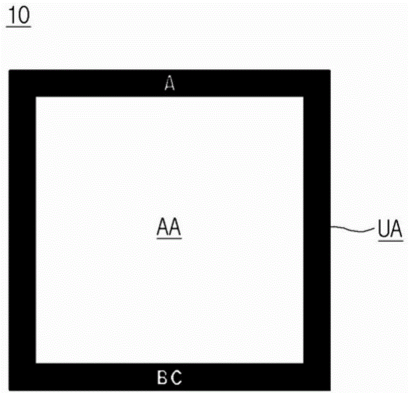
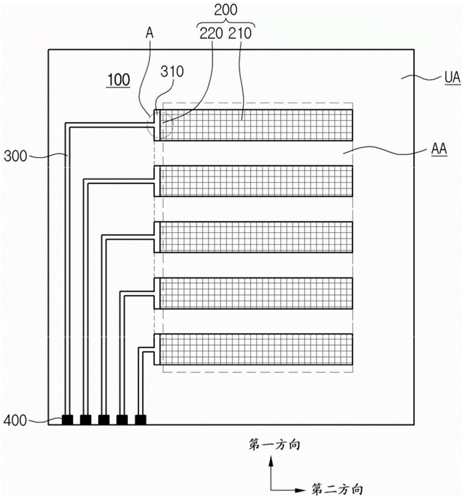
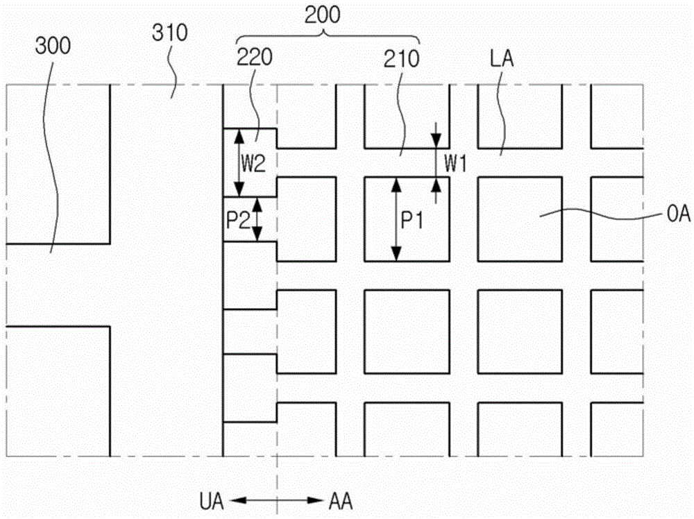
[0030] In the following, reference will be made to Figure 1 to Figure 3 The touch wind...


PUM


Abstract

Disclosed is a touch window including a sensing electrode (200) to sense a position, and a wire (300) to electrically connect the sensing electrode (200). A width of the sensing electrode (200) is variable in the sensing electrode (200).

Description

technical field [0001] The present disclosure relates to a touch window and a touch device including the touch window. Background technique [0002] Recently, a touch panel that performs an input function by touching an image displayed on a touch device with an input device such as a stylus or a finger has been applied to various electronic products. [0003] Touch panels can typically be classified into resistive touch panels and capacitive touch panels. In a resistive touch panel, a position of a touch point is detected by detecting a change in resistance according to a connection between electrodes when pressure is applied to an input device. In a capacitive touch panel, the position of a touch point is detected by detecting a change in capacitance between electrodes when a user's finger touches on the capacitive touch panel. Recently, capacitive touch panels have drawn attention in smaller models in consideration of convenience in manufacturing schemes and sensing powe...

Claims


Application Information

Patent Timeline
IPC IPC(8): G06F3/041G06F3/044
CPCG06F3/044G06F3/0445G06F3/041G06F3/045
Inventor 李裁洪具赞奎金贤秀辛俊植梁峻赫
Owner LG INNOTEK CO LTD
Why Eureka
Try Eureka