Laser timing guide rail

A guide rail and laser technology, applied in educational appliances, instruments, teaching models, etc., can solve the problem of no improvement, and achieve the effect of simplifying the optical path, realizing timing and speed measurement, and reducing the number of receivers

Inactive Publication Date: 2015-04-29
HUIZHOU UNIV
View PDF8 Cites 2 Cited by
  • Summary
  • Abstract
  • Description
  • Claims
  • Application Information

AI Technical Summary

Problems solved by technology

[0002] Some ordinary physical kinematics experimental teaching aids have not been improved for many years. For example, the Chinese patent named digital timing guide rail experiment trolley, its application number is 90216765.0, a digital timing guide rail experimental trolley for measuring time in ordinary physical kinematics experiments

Method used


Image

  • Laser timing guide rail

Examples


Embodiment Construction

[0017] In order to better illustrate the purpose, technical solutions and advantages of the present invention, the present invention will be further described below in conjunction with the accompanying drawings and specific embodiments.

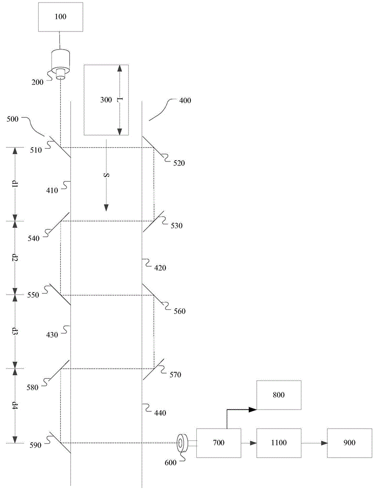
[0018] One embodiment of the present invention is a laser timing guide rail, which includes a laser power supply, a semiconductor laser, a guide rail, a high reflection mirror group, a photosensitive tube, and a recording device; for example, the recording device includes an amplifier; The device also includes a computer and the like connected to the amplifier. Alternatively, the recording device can also be other devices or circuits capable of recording the output signal of the photosensitive tube; Amplified by the amplifier, it is output as a recording signal.

[0019] The laser power supply is connected to the semiconductor laser to provide power for the semiconductor laser; the high reflection mirror group includes a number of high refle...


PUM


Abstract

The invention provides a laser timing guide rail. The laser timing guide rail comprises a laser unit power supply, a semi-conductor laser unit, a guide rail body, a reflecting mirror group, a light sensitive tube and an amplifier, wherein the laser unit power supply is connected with the semi-conductor laser unit; the reflecting mirror group comprises a plurality of reflecting mirrors, all the reflecting mirrors are arranged on two sides of the guide rail body respectively, and the reflecting mirrors and the semi-conductor laser unit form a light path; all the reflecting mirrors sequentially reflect lasers of the semi-conductor laser unit respectively and output the lasers to the light sensitive tube; an output end of the light sensitive tube is connected with the amplifier. Thus, the timing guide rail, simplification of the light path, reduction of the number of receivers as well as effective realization of timing and speed measurement of fast moving objects are realized with the laser technology, and the laser timing guide rail can be matched with multiple signal receiving devices for use and used as a teaching demonstration to enable students to learn natural physical science.

Description

technical field [0001] The invention relates to the experimental design of physics teaching, in particular to a laser timing guide rail. Background technique [0002] Some common physical kinematics experimental teaching aids have not been improved for many years. For example, the Chinese patent titled digital timing rail experiment trolley, whose application number is 90216765.0, is a digital timing rail experimental trolley for measuring time in ordinary physical kinematics experiments. The feature of the present invention is that two slidable switches for controlling the second function of the electronic watch are installed in the shallow groove on the edge of the guide rail plate. A control element for realizing the control of the second function switch used in conjunction with the control switch of the second function switch of the electronic watch is housed on the bracket, and a single-core jack is connected to the second function switch of the electronic watch in para...

Claims


Application Information

Patent Timeline
Patent Type & Authority Applications(China)
IPC IPC(8): G09B23/06
CPCG09B23/06
Inventor 王健海蔡昭权
Owner HUIZHOU UNIV
Why Eureka
Try Eureka