Antenna system and base station

An antenna system and antenna technology, applied in the direction of antenna, antenna coupling, antenna array, etc.

Active Publication Date: 2015-04-29
HUAWEI TECH CO LTD
View PDF6 Cites 4 Cited by
  • Summary
  • Abstract
  • Description
  • Claims
  • Application Information

AI Technical Summary

Problems solved by technology

[0004] The embodiment of the present invention provides an antenna system and a base station to solve the problem that multiple columns of antennas with small intervals can only provide narrow beams, and meet the requirements of the antenna system to provide both wide beams and narrow beams

Method used


Image

  • Antenna system and base station
  • Antenna system and base station
  • Antenna system and base station

Examples


Embodiment Construction

[0057] In order to make the purpose, technical solutions and advantages of the embodiments of the present invention clearer, the technical solutions in the embodiments of the present invention will be clearly and completely described below in conjunction with the drawings in the embodiments of the present invention. Obviously, the described embodiments It is a part of embodiments of the present invention, but not all embodiments. Based on the embodiments of the present invention, all other embodiments obtained by persons of ordinary skill in the art without creative efforts fall within the protection scope of the present invention.

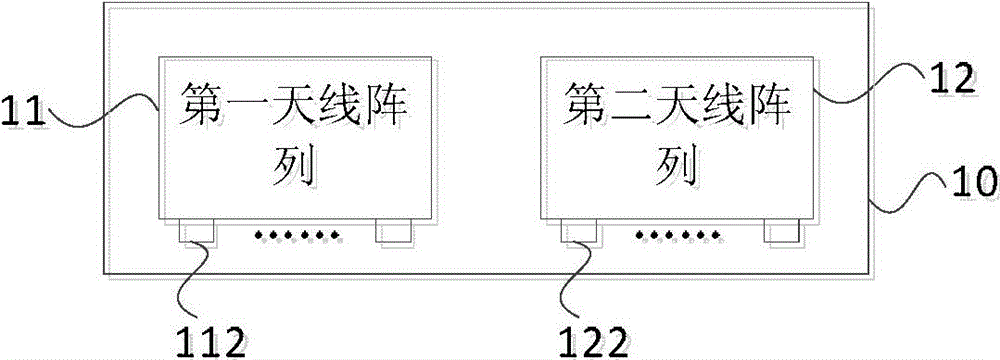
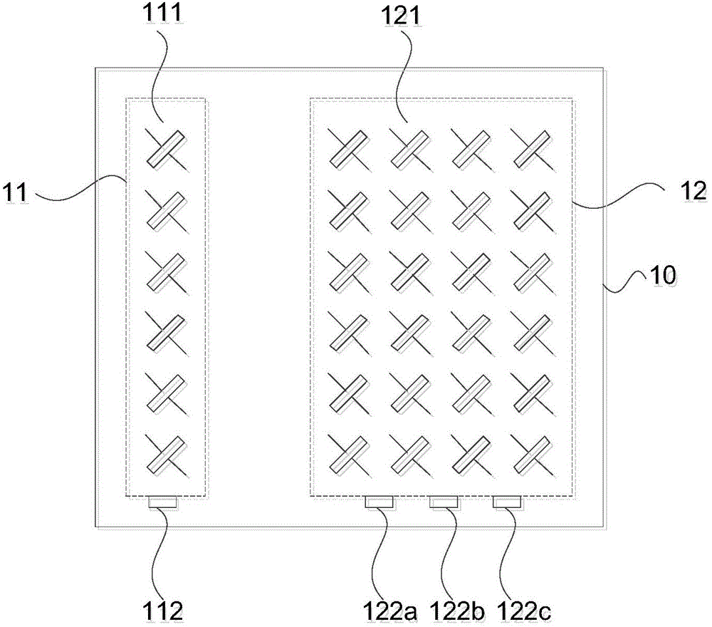
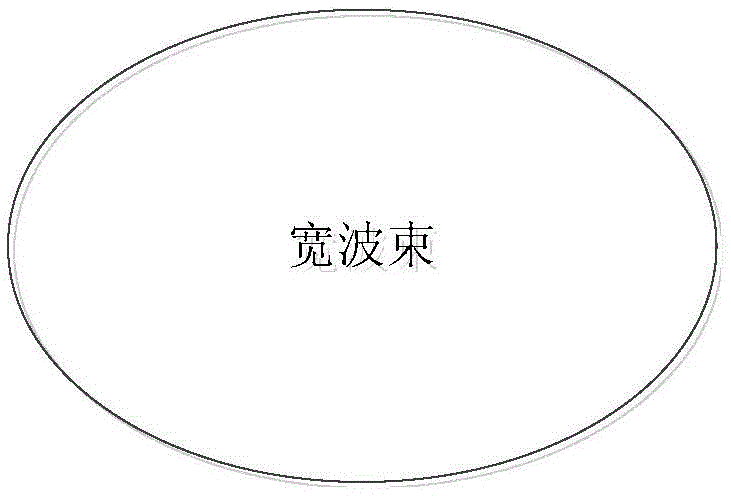
[0058] figure 1 It is a schematic structural diagram of Embodiment 1 of the antenna system of the present invention, such as figure 1As shown, the antenna system 10 of this embodiment may include: a first antenna array 11 and a second antenna array 12, wherein the first antenna array 11 is used to form a wide beam coverage; the second antenna arr...


PUM


Abstract

The embodiment of the present invention provides an antenna system and a base station. The antenna system of the present invention includes: a first antenna array for forming wide beam coverage and a second antenna array for forming narrow beam coverage; and the fist antenna array includes at least one row antenna, each row antenna provides at least a wide beam port, the second antenna array includes at least two rows antennas, and the second antenna array provides at least one narrow beam port. The embodiment of the present invention solves a problem that the small interval multi-row antennas can only provide narrow beam, and meets the requirement that the antenna system provides wide beam and narrow beam simultaneously.

Description

technical field [0001] Embodiments of the present invention relate to communication technologies, and in particular to an antenna system and a base station. Background technique [0002] With the development of communication technology, the layout of antennas faces the dual challenges of limited site space and small capacity. The antennas support multiple systems at the same time, such as supporting Global System For Mobile Communications (Global System For Mobile Communications, hereinafter referred to as GSM), Universal Mobile Telecommunications System (hereinafter referred to as UMTS) and Long Term Evolution (hereinafter referred to as LTE) systems have become an inevitable trend. The existing small-interval multi-column antenna layout technology realizes space division multiple access by splitting a single beam into multiple beams, and achieves the purpose of improving the capacity of the antenna. [0003] However, this antenna layout technology can only provide narrow ...

Claims


Application Information

Patent Timeline
Patent Type & Authority Applications(China)
IPC IPC(8): H01Q21/30H01Q1/52
CPCH01Q25/002H01Q1/246H01Q1/521H01Q21/0006H01Q21/061H01Q21/08
Inventor 赵建平
Owner HUAWEI TECH CO LTD
Why Eureka
Try Eureka