Wireless charging system with double detecting circuits

A wireless charging and dual detection technology, applied in electromagnetic wave systems, current collectors, electric vehicles, etc., can solve problems such as signal confusion and unclear

Active Publication Date: 2015-04-29
国智电子股份有限公司
View PDF3 Cites 0 Cited by
  • Summary
  • Abstract
  • Description
  • Claims
  • Application Information

AI Technical Summary

Problems solved by technology

[0005] However, if the control of the wireless charging system needs to be adjusted according to the captured signal, the signal may be confused due to various factors, so a system that can ensure a clear signal is required

Method used


Image

  • Wireless charging system with double detecting circuits
  • Wireless charging system with double detecting circuits
  • Wireless charging system with double detecting circuits

Examples


Embodiment Construction

[0090] Various embodiments of the invention will now be described. The following description provides specific implementation details of the present invention so that readers can fully understand the implementation of these embodiments. However, it will be understood by those skilled in the art that the present invention may be practiced without these details. In addition, some well-known structures or functions will not be described in detail in order to avoid unnecessary confusion of related descriptions among various embodiments, and the terms used in the following description will be interpreted in the broadest reasonable manner, even if Used in conjunction with a detailed description of a particular embodiment of the invention.

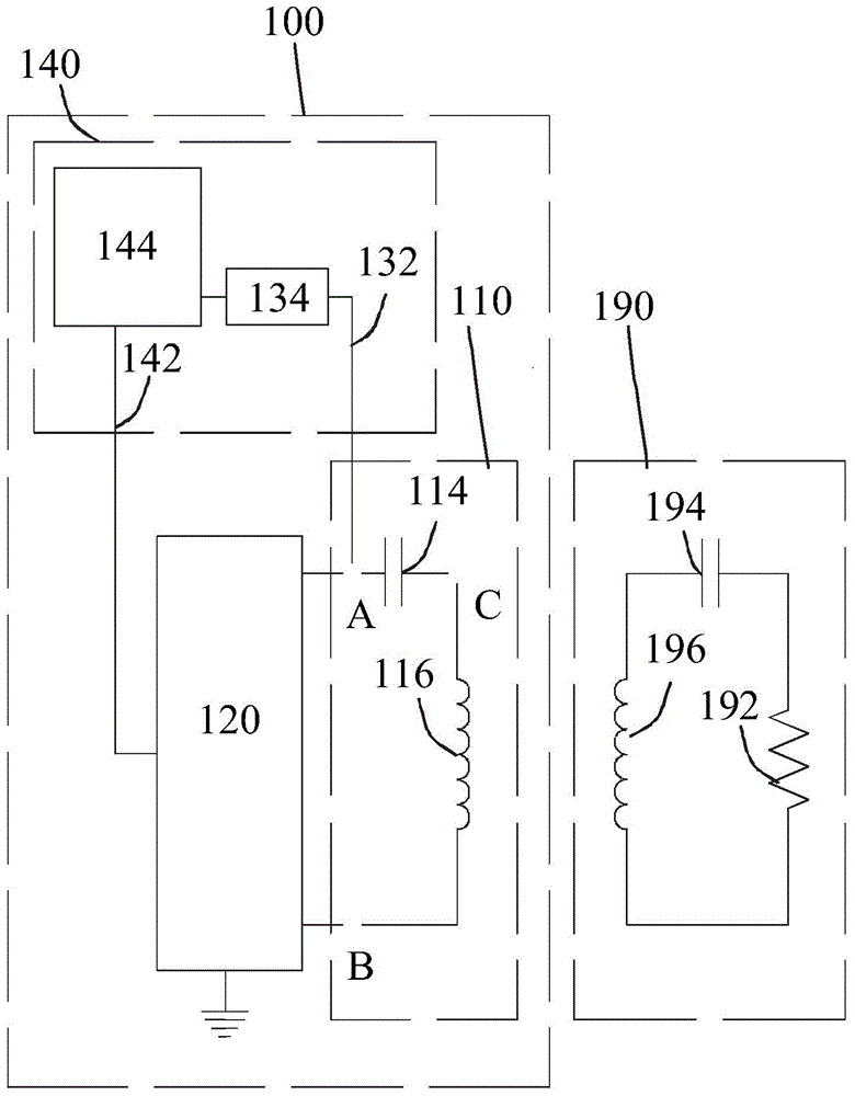
[0091] figure 1 It is a schematic diagram of a wireless charging system 100 and a receiving device 190 according to an embodiment of the present invention. Wherein, the receiving end device 190 may be a device containing a rechargeable battery...


PUM


Abstract

A wireless charging system with double detecting circuits comprises a detecting circuit connected to an inductive loop to detect the induced electric field of the inductive loop; an auxiliary detection circuit connected to a power loop to detect the induced electric field of the power loop, wherein when the waveform detected by the detecting circuit is not applicable, it is replaced by the waveform detected by the auxiliary detecting circuit in order to determine the condition of the electrical receiver device and thus adjust the output to the inductive loop from the power loop.

Description

technical field [0001] The present invention relates to a charging system, in particular to a wireless charging system. Background technique [0002] Wireless charging is also called inductive charging and non-contact inductive charging. It uses near-field induction, that is, inductive coupling, to transmit energy from the power supply equipment to the power-consuming device. The device uses the received energy to charge the battery and simultaneously for its own operation. Since energy is transmitted between the charger and the power-consuming device through inductive coupling, there is no need for wires to connect the two, so that both the charger and the power-consuming device can have no exposed conductive contacts. [0003] Specifically, there is a coil in the wireless charging charger, which is driven by alternating current to generate an alternating electromagnetic field. There is another coil in the electric device that receives the alternating electromagnetic field...

Claims


Application Information

Patent Timeline
Patent Type & Authority Applications(China)
IPC IPC(8): H02J7/00H02J17/00
CPCH02J7/025H02J50/12H02J50/10H02J7/00
Inventor 黄国展李哲颖
Owner 国智电子股份有限公司
Why Eureka
Try Eureka