Electric energy dispatching charging system and method

A charging system and charging method technology, applied in electric vehicle charging technology, charging stations, battery circuit devices, etc., can solve the problems of low charging efficiency, low effective utilization of resources, and no solution to idle charging supply.

Active Publication Date: 2015-04-29
SHENZHEN CLOU ELECTRONICS +1
View PDF4 Cites 21 Cited by
  • Summary
  • Abstract
  • Description
  • Claims
  • Application Information

AI Technical Summary

Problems solved by technology

When the electric vehicle is charged to a certain level, its charging demand will drop, but because the charging pile is an independent charging module, the redundant charging supply is only idle because there is only a single charging interface, resulting in a relatively low overall charging efficiency
Independent charging module, the failure of the charging module will have a greater impact, and the failure of any charging module will directly affect the charging performance of the charging pile
[0003] Some charging piles can provide two charging interfaces, but the charging modules are simply divided into two groups, each connected to a charging interface, which does not solve the problem of low overall charging efficiency due to idle charging supply
Moreover, the internal layout of this charging pile is cumbersome, the overall volume is very large, and the effective utilization rate of resources is not high

Method used


Image

  • Electric energy dispatching charging system and method
  • Electric energy dispatching charging system and method
  • Electric energy dispatching charging system and method

Examples


Embodiment Construction

[0037] In order to facilitate the understanding of the present invention, the present invention will be described more fully below with reference to the associated drawings. Preferred embodiments of the invention are shown in the accompanying drawings. However, the present invention can be embodied in many different forms and is not limited to the embodiments described herein. On the contrary, these embodiments are provided to make the understanding of the disclosure of the present invention more thorough and comprehensive.

[0038] Unless otherwise defined, all technical and scientific terms used herein have the same meaning as commonly understood by one of ordinary skill in the technical field of the invention. The terms used herein in the description of the present invention are for the purpose of describing specific embodiments only, and are not intended to limit the present invention. As used herein, the term "and / or" includes any and all combinations of one or more of ...


PUM


Abstract

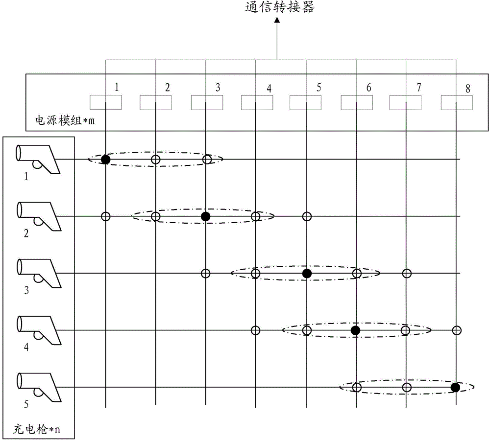
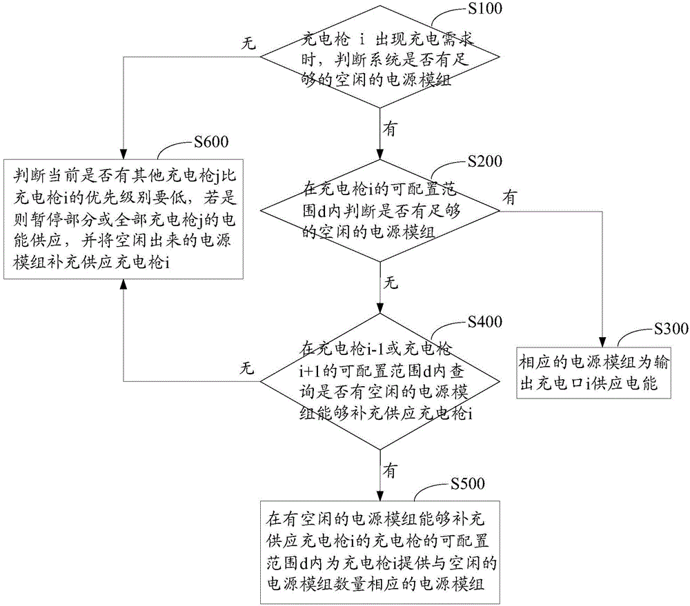
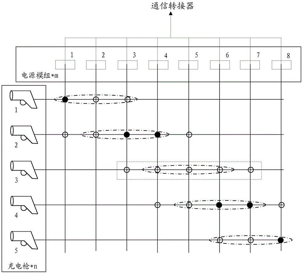
The invention relates to an electric energy dispatching charging system. According to the electric energy dispatching charging system, a power supply module can be reasonably and flexibly distributed to each charging gun conveniently by reasonably setting an electric energy output node of each charging gun. As a mode that the electric energy output node of each charging gun is more averagely set and the power supply modules are flexibly distributed is adopted, the system can reduce the vacancy rate of the power supply modules, and can realize output efficiency of all power supply modules maximally. Through the system, the unified background control of the power supply modules is realized, so that not only is low vacancy rate of the power supply modules easily realized, but also a charging mode of using one charging post to charge multiple electric devices can be realized, the cost is low, the expansibility is high, and the site utilization ratio is high. The invention further discloses an electric energy dispatching charging method.

Description

technical field [0001] The invention relates to the technical field of charging, in particular to an electric energy scheduling charging system and an electric energy scheduling charging method. Background technique [0002] In the context of advocating energy conservation and emission reduction, the promotion of electric vehicles has become more and more important, and supporting facilities for electric vehicles must also be established. Most traditional charging equipment, such as charging piles, can only provide a single charging interface, so the utilization rate of the site is not high. When the electric vehicle is charged to a certain level, its charging demand will drop. However, since the charging pile is an independent charging module, the redundant charging supply can only be idle because there is only a single charging interface, resulting in a relatively low overall charging efficiency. Independent charging modules, the failure of the charging module has a great...

Claims


Application Information

Patent Timeline
Patent Type & Authority Applications(China)
IPC IPC(8): H02J7/00
CPCB60L53/30B60L53/38B60L53/53B60L53/54B60L53/60Y02T10/70Y02T10/7072Y02T90/12
Inventor 赵颖
Owner SHENZHEN CLOU ELECTRONICS
Why Eureka
Try Eureka