Electrical highway charging system
A technology for electrified roads and charging systems, applied in the direction of electric vehicle charging technology, charging stations, electrical components, etc., can solve the problems of inability to realize long-distance driving, low charging efficiency, and long time consumption, and achieve high economic and social benefits. High charging efficiency and reasonable design effect
- Summary
- Abstract
- Description
- Claims
- Application Information
AI Technical Summary
Problems solved by technology
Method used
Image
Examples
Embodiment 1
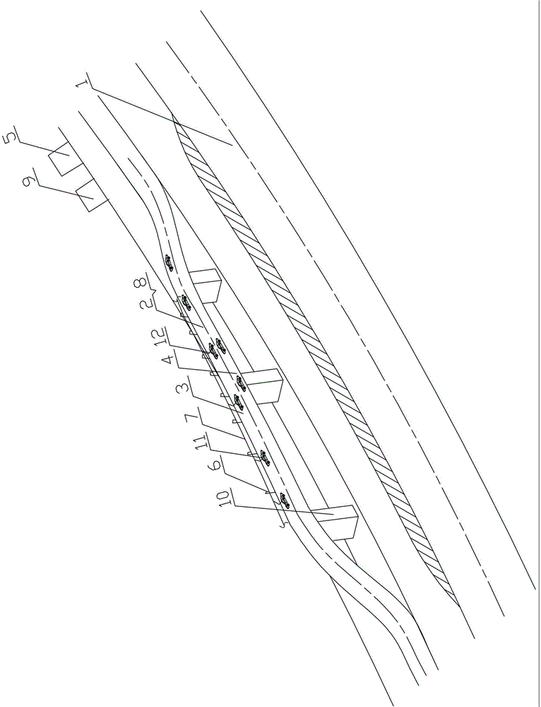
[0019] see figure 1 , an electrified highway charging system in this embodiment is to draw a section of electrified charging highway 2 with a length of 10 kilometers parallel to the existing highway 1 every 50 kilometers on the existing highway 1 (especially the expressway), so The width of the electrified charging road 2 is designed to drive two car lanes side by side in one direction (one of which is the charging lane 3 and the other is the spare lane 4), and a charging network is arranged beside the electrified charging road, and the charging network includes a substation 5, a 9. Elevated pole 6 and overhead cable 7. The elevated pole 6 is located on one side of the electrified charging road 2. The overhead cable 7 is overhead above the electrified charging road 2 through the elevated pole 6. The overhead cable 7 communicates with the substation 5.
[0020] In order to ensure the safety of pedestrians and the existing highway 1, the electrified charging highway 2 is built o...
Embodiment 2
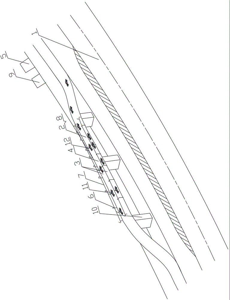
[0025] see figure 2 , an electrified road charging system in this embodiment is to draw a section of electrified charging road 2 with a length of 20 kilometers parallel to the existing road 1 every 100 kilometers on the existing road 1, and the electrified charging road 2 The width is designed to be 3 car lanes driving side by side in one direction (the lanes near the two sides of the charging road are the charging lane 3, and the lane in the middle is the backup lane 4), and a charging network is arranged next to the electrified charging road, and the charging network includes substation 5 , a rectifier 9, an elevated pole 6 and an overhead cable 7, the elevated pole 6 is located on one side of the electrified charging road 2, the overhead cable 7 is overhead above the electrified charging road 2 through the elevated pole 6, the overhead cable 7 and the substation 5 connected.
[0026] In order to ensure the safety of pedestrians and the existing highway 1, the electrified ...
Embodiment 3
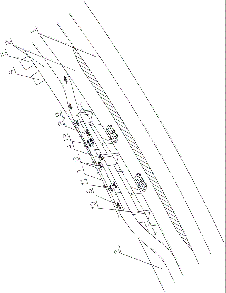
[0031] see image 3 , Figure 4 , an electrified road charging system in this embodiment is to draw a section of electrified charging road 2 with a length of 20 kilometers parallel to the existing road 1 every 70 kilometers on the existing road 1, and the electrified charging road 2 The width is designed to be 3 car lanes driving side by side in one direction (the lanes near the two sides of the charging road are the charging lane 3, and the lane in the middle is the backup lane 4), and a charging network is arranged next to the electrified charging road, and the charging network includes substation 5 , a rectifier 9, an elevated pole 6 and an overhead cable 7, the elevated pole 6 is located on one side of the electrified charging road 2, the overhead cable 7 is overhead above the electrified charging road 2 through the elevated pole 6, the overhead cable 7 and the substation 5 connected.
[0032] In order to ensure the safety of pedestrians and the existing highway 1, the e...
PUM
 Abstract
Description
Claims
Application Information
 - R&D
- Intellectual Property
- Life Sciences
- Materials
- Tech Scout
- Unparalleled Data Quality
- Higher Quality Content
- 60% Fewer Hallucinations
Browse by: Latest US Patents, China's latest patents, Technical Efficacy Thesaurus, Application Domain, Technology Topic, Popular Technical Reports.
© 2025 PatSnap. All rights reserved.Legal|Privacy policy|Modern Slavery Act Transparency Statement|Sitemap|About US| Contact US: help@patsnap.com


