Eureka AIR delivers breakthrough ideas for toughest innovation challenges, trusted by R&D personnel around the world.

Method for obtaining array antenna receiving signal power error range

A technology of received signal power and error range, applied in receiver monitoring, transmission monitoring, electrical components, etc., can solve the problems of not guaranteeing the robustness of the array, unrealizable measurement, not comprehensively considering the amplitude, and the position error of the array element.

Inactive Publication Date: 2015-04-29
UNIV OF ELECTRONICS SCI & TECH OF CHINA
View PDF5 Cites 6 Cited by
  • Summary
  • Abstract
  • Description
  • Claims
  • Application Information

AI Technical Summary

Problems solved by technology

However, due to the unrealizable measurement caused by infinite combinations of control point values ​​when the error threshold is given, the above method is not completely reliable, and the robustness of the array cannot be guaranteed
In addition, the existing antenna design method can only be designed according to the ideal array, and once there is an error in the antenna, the designed antenna pattern's sidelobe level, main lobe width, main lobe directivity and other factors will not meet the design requirements
However, the existing power error analysis method only considers one factor of the amplitude error, and does not comprehensively consider the situation that there are errors in the amplitude and the position of the array element at the same time.

Method used


Image

  • Method for obtaining array antenna receiving signal power error range
  • Method for obtaining array antenna receiving signal power error range
  • Method for obtaining array antenna receiving signal power error range

Examples


Embodiment Construction

[0027] The specific implementation manners of the present invention will be illustrated below with reference to the accompanying drawings.

[0028] Step 1. Set the relevant parameters of the linear array according to the actual situation, and thus obtain the model of the array factor.

[0029] Step 1-1. According to the actual situation of the array, use the Taylor synthesis method to determine the reference value α of the array received signal amplitude n , and its measurable upper and lower errors with and from this we get the amplitude A n The upper bound of the error: and lower bounds: sup { A n } = α n - ϵ n { inf } ( n = 0,1 , . . . , ...


PUM


Abstract

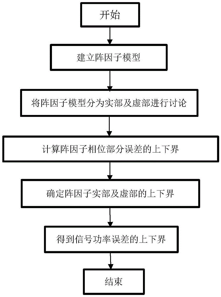
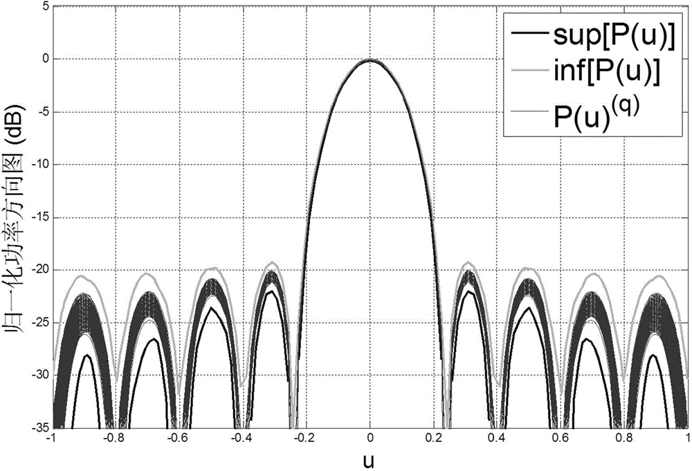
The invention belongs to the category of array signal processing of antennas receiving wireless transmission signals, discloses a method for obtaining the array antenna receiving signal power range, and particularly relates to a method for calculating the power error generated when an antenna receives signals when array errors exist. The method comprises the steps that according to measured array receiving signal amplitude errors and array element position errors, an array factor model is determined, the array factor model is made to deform to obtain a real part and an imaginary part, and then the upper and lower bounds of the array receiving signal amplitude and phase part errors are obtained, so that the upper and lower bounds of the array factor real and imaginary parts are obtained, and finally the upper and lower bounds of the signal power errors are obtained through calculation. Accordingly, the obtained antenna receiving signal power errors are more accurate, and major parameters such as the minor lobe level, the main lobe width and the array direction coefficient can be effectively controlled in the antenna design.

Description

technical field [0001] The invention belongs to the field of antenna array signal processing for receiving wireless transmission signals, in particular to a power error calculation method for antenna receiving signals when array errors exist. Background technique [0002] Modern wireless communication systems require antennas to ensure high quality and reliable data transmission. In many practical applications, the pattern generated by the array requires high directivity of the main lobe and low side lobes. To this end, some methods have been proposed to analyze the appropriate values ​​of the control points (such as amplification, phase shifter, time delay, etc.) of the relevant beamforming network. However, due to manufacturing tolerances, every element in the antenna system, including the radiating elements and the control points of the beamforming network, does not exactly match the ideal. This unavoidable error causes radiation beam shifts and performance degradation ...

Claims


Application Information

Patent Timeline
IPC IPC(8): H04B17/21H04B17/327
Inventor 张瑛赵丹旎陈垠江康宁赵华鹏
Owner UNIV OF ELECTRONICS SCI & TECH OF CHINA
Why Eureka
Eureka Blog
Learn More