An aviation bomb clamping device based on the principle of double-slider mechanism

A clamping device and double-slider technology, which is applied in fire rescue and other fields, can solve problems such as vibration, mutual collision, and affecting the smooth operation of aerial bomb delivery, and achieve the effect of simple structure and guaranteed delivery stability

Active Publication Date: 2017-06-20
HARBIN ENG UNIV
View PDF4 Cites 0 Cited by
  • Summary
  • Abstract
  • Description
  • Claims
  • Application Information

AI Technical Summary

Problems solved by technology

[0003] Now there is a patent named "Integrated Loading Module for Forest Fire Fighting Aerial Bombs", which proposes an idea of ​​integrated loading, which solves the installation problem of the aerial bomb group to a certain extent through binding straps and hoisting plates. The guide cylinder can also play a certain limit and fix tasks in a small range. However, the air environment is complex, and the aircraft needs to face the influence of strong airflow during flight. In the case of the overall modular assembly of the aerial bomb, although it can guarantee Certain installation and fixing requirements are required, but there are gaps between the bombs and a small range of activity space in the protective tube between the bomb frames. When flying in the air, the bombs will inevitably vibrate and may even collide with each other. At the same time, the entire weight of the aerial bomb group is transmitted to the delivery mechanism through various connections. The friction and pressure faced by the local connections of the delivery mechanism are very large, which can easily affect the smooth progress of the aerial bomb delivery operation. Combining fixation, clamping, limited positioning, and delivery tasks into one, making a mechanism that is convenient for delivery has become an important topic and direction

Method used


Image

  • An aviation bomb clamping device based on the principle of double-slider mechanism
  • An aviation bomb clamping device based on the principle of double-slider mechanism
  • An aviation bomb clamping device based on the principle of double-slider mechanism

Examples


Embodiment Construction

[0026] The present invention is described in more detail below in conjunction with accompanying drawing example:

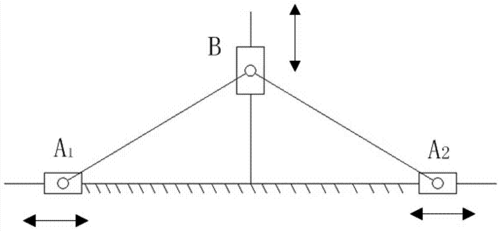
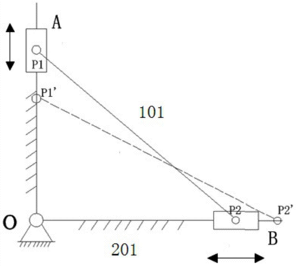
[0027] combine Figure 1-8 , the basic type of planar four-bar linkage and its evolution, see figure 1 , the figure shows a four-bar mechanism with two moving pairs, and its working principle is shown in figure 2 , is composed of double sliders A, B, connecting rod 101 and rack 201, p1 is the center of slider A, p2 is the center of slider 2, p1' is the center of slider A after moving, p2' is the center of slider A The center of block B after moving;

[0028] By the triangle theorem, op 1 2 +op 2 2 =p 1 p 2 2 、op 1 ' 2 +op 2 ' 2 =p 1 'p 2 ' 2

[0029] And it is known that the connecting rod length is constant, so p 1 p 2 =p 1 'p 2 ',

[0030] roll out: p 2 p 2 '=op 2 '-op 2

[0031] It can be seen from the formula that p 2 ' point trajectory and p 2 p 2 'The length is mainly determined by p 1 ,p 2 and p 1 'Three point parameters ...


PUM


Abstract

The invention aims to provide a bomb clamping device based on the principle of a double-slider mechanism. When arriving at the overhead of a fire scene, a host computer sends a signal to control the rotation of a rotary motor, in order to drive a rotating shaft coaxial with the rotary motor to rotate, the rotating shaft drives a gear in key fit with the rotating shaft to move, the gear transmits the movement to a gear rack, a main piston rod moves downwards with the movement of the gear rack, meanwhile the movement is transmitted to an auxiliary piston rod I and an auxiliary piston rod II by a connecting rod, the auxiliary piston rod I and the auxiliary piston rod II advance with a straining ring, a fire extinguishing bomb fixed by the straining ring moves along a slide way along the feeding movement of the straining ring, after moving for a segment of distance, when the straining ring and the circle center of a discharge opening are approximately coaxial, the fire extinguishing bomb deviates from the tail end of the slide way, and the fire extinguishing bomb is discharged under the self-gravity environment of the fire extinguishing bomb. According to the bomb clamping device provided by the invention, a connecting rod mechanism is evolved to the double-slider mechanism, so that a series of actions of clamping, propelling and discharging the fire extinguishing bomb can be successfully completed.

Description

technical field [0001] The invention relates to a fire extinguishing device, in particular to a clamping and throwing device of a forest fire extinguishing device. Background technique [0002] Forest fire is a serious worldwide natural disaster, which has caused immeasurable losses to human resources and the environment. However, with the advancement of human technology, helicopters, an advanced transportation tool with a large carrying capacity, are being used for forest fire prevention. , Fire fighting is playing an increasingly important role. At present, at home and abroad, for extinguishing the forest crown fire, it is mainly carried by fixed-wing aircraft or helicopters to carry fire extinguishing agent or water to spray from high altitude. Due to the strong updraft and turbulence over the fire field, the fire extinguishing agent is dispersed by the strong high-temperature airflow, and the fire extinguishing agent falls on the tree crowns is very little, and the fire...

Claims


Application Information

Patent Timeline
Patent Type & Authority Patents(China)
IPC IPC(8): A62C3/02A62C19/00
CPCA62C3/025A62C19/00
Inventor 刘少刚吴长龙张驰航郑大勇曾杏姚磊孔令宇程千驹宋建鑫吴伟峰
Owner HARBIN ENG UNIV
Why Eureka
Try Eureka