Batching system for gas state materials

A batching system, a technology for gaseous materials, applied in mixer accessories, gas and gas/vapor mixing, dissolving and other directions, can solve the problems of uneven composition and content of materials flowing out of the container, improve control accuracy and control difficulty, and meet the needs of large materials The effect of leak rate

Inactive Publication Date: 2015-05-06
RES INST OF PHYSICAL & CHEM ENG OF NUCLEAR IND
View PDF4 Cites 1 Cited by
  • Summary
  • Abstract
  • Description
  • Claims
  • Application Information

AI Technical Summary

Problems solved by technology

But simply put WF 6 , HF, N 2 , O 2 When standing in a closed container, the above-mentioned gases will be distributed in layers instead of uniformly mixed, resulting in uneven composition and content of the materials flowing out of the container. Therefore, the above-mentioned batching method cannot meet the existing needs

Method used


Image

  • Batching system for gas state materials
  • Batching system for gas state materials
  • Batching system for gas state materials

Examples


Embodiment Construction

[0028] Below, the present invention is described in detail with reference to accompanying drawing and embodiment:

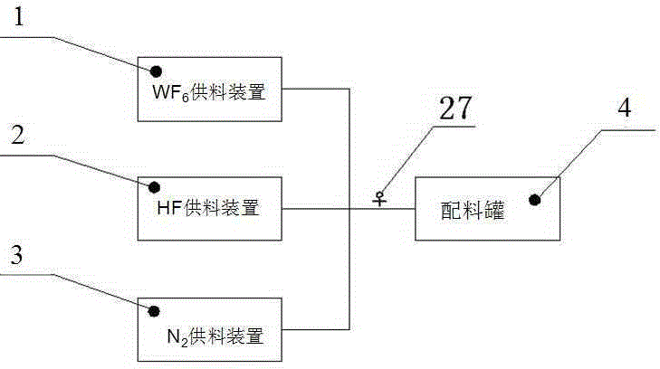
[0029] like figure 1 As shown, a batching system for gaseous materials, including WF 6 Feeding device 1, HF feeding device 2, N 2 The feeding device 3 is connected in parallel to the pipeline 6 and communicates with the batching tank 4 .

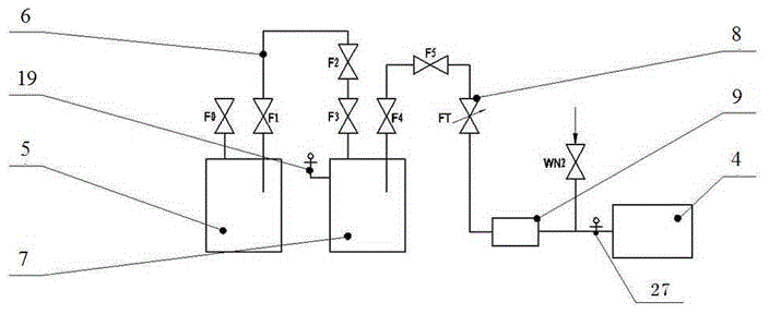
[0030] like figure 2 shown, the WF 6 Feed unit 1 includes WF 6 Feed container 5, WF 6 The first interface of the supply container 5 is provided with an F0 valve, WF 6 Feed container 5 with WF 6 The pipelines 6 between the surge tanks 7 are sequentially provided with F1~F3 valves, WF 6 The pipeline 6 between the surge tank 7 and the batching tank 4 is provided with F4 valve, F5 valve, manual fine-tuning valve 8, WF 6 Mass flow meter 12 and No. VII pressure gauge 27.

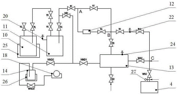
[0031] so image 3 As shown, the HF feeding device 2 described includes a HF feeding container 10, the first interface of the HF feeding container 10 i...


PUM


Abstract

The invention discloses a batching system for gas state materials. The batching system comprises a WF6 material feeding device, an HF material feeding device and an N2 material feeding device, which are communicated with a batching tank, wherein the WF6 material feeding device comprises a WF6 material feeding container, a WF6 surge tank, a WF6 mass flowmeter, and the batching tank, which are sequentially communicated through a pipeline and valves; the HF material feeding device comprises an HF material feeding container, an HF surge tank, an HF mass flowmeter, a standard volume tank and the batching tank, which are sequentially communicated through the pipeline and the valves; the N2 material feeding device comprises an N2 material feeding container, an N2 surge tank, an N2 mass flowmeter, a standard volume tank and the batching tank, which are sequentially communicated through the pipeline and the valves. According to the batching system disclosed by the invention, the materials can be quantitatively adjusted and supplied; the material flows fed to the separation unit and the content of the materials can be ensured to be invariable; the flow of the WF6 can be controlled by a mass method, and the flows of the HF and the N2 are controlled by a volumetric method, so that the flow control precision can be improved, and the control difficulty can be reduced; as a valve W7 and a valve N4 are utilized, the batching system can meet the requirement on high leak rate of the material.

Description

technical field [0001] The invention belongs to a batching device, in particular to a batching system for gaseous materials. Background technique [0002] on WF 6 During the production process, there will be a certain amount of light impurities, such as HF, N 2 , O 2 etc., produced or leaked into the product, so the output WF 6 The material is purified. [0003] In the separation of the above WF 6 In the process of experimental research with light impurities, it is necessary to simulate the raw materials in the production device, and the results of the quantitative ratio will directly affect the objectivity and accuracy of the test results. But simply put WF 6 , HF, N 2 , O 2 When standing in a closed container, the above-mentioned gases will be distributed in layers instead of uniformly mixed, resulting in uneven composition and content of the materials flowing out of the container. Therefore, the above-mentioned batching method cannot meet the existing needs. Con...

Claims


Application Information

Patent Timeline
Patent Type & Authority Applications(China)
IPC IPC(8): B01F15/04B01F3/02B01F23/10
Inventor 刘巍韩莉果周勃赫梓宇
Owner RES INST OF PHYSICAL & CHEM ENG OF NUCLEAR IND
Why Eureka
Try Eureka