Self-locking type safety clamp capable of being rapidly mounted and detached

A self-locking and safe technology, applied in the direction of friction clamping detachable fasteners, connecting components, mechanical equipment, etc., can solve the safety hazards of installation fixtures, insufficient bolt tightening, easy loss of bolts and other problems. Achieving the effect of avoiding potential safety hazards, convenient assembly and disassembly, and avoiding man-made losses

Inactive Publication Date: 2015-05-06
CHINA CONSTR STEEL STRUCTURE CORP LTD
View PDF7 Cites 2 Cited by
  • Summary
  • Abstract
  • Description
  • Claims
  • Application Information

AI Technical Summary

Problems solved by technology

[0010] The purpose of the present invention is to overcome the above disadvantages and provide a self-locking fast installation and disassembly safety fixture, which solves the problems of cumbersome installation and disassembly procedures of existing fixtures and potential

Method used


Image

  • Self-locking type safety clamp capable of being rapidly mounted and detached
  • Self-locking type safety clamp capable of being rapidly mounted and detached
  • Self-locking type safety clamp capable of being rapidly mounted and detached

Examples


Embodiment 1

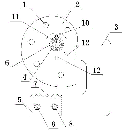
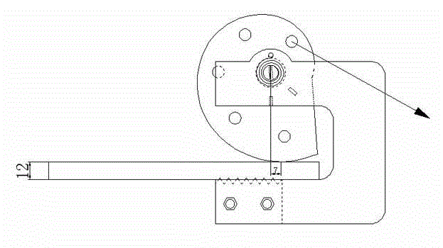
[0032] in accordance with image 3 , The safety net clamp of the present embodiment works on a flange steel plate with a plate thickness of 12mm.

[0033] Installation steps: Rotate the locking part counterclockwise to open, insert the opening of the U-shaped splint against the flange steel plate, then release the locking part, and use the elastic force of the shaft spring itself to fix the clamp on the flange steel plate. After the fixing is complete, select as image 3 As shown in the lanyard hole, the installation is completed by hanging the end of the safety net in the lanyard hole. At this time, the horizontal distance from the tangent point between the outer edge of the locking member and the steel plate to the center of the rotating shaft of the locking member is 7 mm.

Embodiment 2

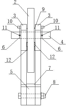
[0035] in accordance with Figure 4 , The safety net clamp of the present embodiment works on a flange steel plate with a plate thickness of 40mm.

[0036] Installation steps: Rotate the locking part counterclockwise to open, insert the opening of the U-shaped splint against the flange steel plate, then release the locking part, and use the elastic force of the shaft spring itself to fix the clamp on the flange steel plate. After the fixing is complete, select as Figure 4 As shown in the lanyard hole, the installation is completed by hanging the end of the safety net in the lanyard hole. At this time, the horizontal distance from the tangent point between the outer edge of the locking member and the steel plate to the center of the rotating shaft of the locking member is 7 mm.


PUM


Abstract

The invention relates to a self-locking type safety clamp capable of being rapidly mounted and detached. The self-locking type safety clamp is characterized by mainly comprises a locking piece (2) and two U-shaped clamping plates (3), wherein the locking piece (2) is mounted between the upper ends of the two U-shaped clamping plates (3) by a pin shaft (4) and is fixedly connected with the pin shaft (4); a torsion spring (6) for controlling a rotary angle of the locking piece (2) is arranged between the two ends of the pin shaft (4) and the two U-shaped clamping plates (3); the locking piece (2) is made of abnormal circular arc steel with a certain outer edge spiral curvature; a plurality of rope hanging holes (1) for hanging a rope end of a safety rope are formed in the surface of the locking piece (2). According to the self-locking type safety clamp capable of being rapidly mounted and detached, the difficulties that a clamp mounting and detaching procedure is complicated and potential safety hazards exist in a clamp mounting process are overcome; the problem that a bolt is not fastened in place in a manual mounting process is avoided and the whole efficiency of safe work is improved.

Description

technical field [0001] The invention relates to the technical field of steel structure fabrication, in particular to a self-locking fast installation and disassembly safety fixture. Background technique [0002] With the development of modernization and the rapid growth of population, the scale of various engineering construction projects is expanding day by day, and high-rise buildings are raised to improve the utilization rate of space. However, the construction height of buildings with concrete structures is limited, which cannot meet the development of modern society. Part of the demand, so many existing high-rise buildings are constructed with steel structures. [0003] During the construction of the outer frame beam, there are multiple working faces on different floors. In order to prevent the falling of sporadic steel and personnel from falling when working on high floors, it is necessary to install safety nets on each floor. Compared with the original method of lay...

Claims


Application Information

Patent Timeline
IPC IPC(8): F16B2/06
CPCF16B2/18
Inventor 唐忠靖方振亚缪佳骏童斯超陈功刘泽宣徐丹
Owner CHINA CONSTR STEEL STRUCTURE CORP LTD
Why Eureka
Try Eureka