Rock axial tension test device and rock axial tension test device

A technology of axial tension and testing equipment, which is applied in the direction of measuring equipment, using stable tension/pressure testing material strength, instruments, etc., can solve the problems that the influence of eccentricity cannot be eliminated, and the influence of eccentricity cannot be completely eliminated, so as to achieve accurate The effect of the test

Inactive Publication Date: 2015-05-06
CHINA HYDROELECTRIC ENGINEERING CONSULTING GROUP CHENGDU RESEARCH HYDROELECTRIC INVESTIGATION DESIGN AND INSTITUTE
View PDF6 Cites 20 Cited by
  • Summary
  • Abstract
  • Description
  • Claims
  • Application Information

AI Technical Summary

Problems solved by technology

Both of the above two methods connect the specimen directly to the testing machine, and the eccentric tension of the rock specimen cannot be avoided during the test.
[0008] (3) "Journal of Rock Mechanics and Engineering" No. 3, 2005 introduced a test method for direct stretching of rocks, designed a tension-compression converter, and bonded the specimen to the tension block with 504 advanced universal adhesive On the other hand, the rock specimens are processed by a grinding machine, but the influence of eccentricity cannot be completely eliminated
[0009] (4) "Journal of Henan Polytechnic University" No. 4, 2006 introduced a direct stretching test device that can add confining pressure. This device uses glue to bond the test piece with the upper and lower pullers, which cannot eliminate the influence of eccentricity.
[0010] To sum up, there is no simple structure in the prior art, which can not only ensure the complete axial alignment of the test piece and the upper and lower pull heads, but also ensure the effective elimination of eccentricity during the tensile test. Rock axial tensile test device and rock axial tensile test method for further improving test accuracy

Method used


Image

  • Rock axial tension test device and rock axial tension test device
  • Rock axial tension test device and rock axial tension test device

Examples


Embodiment Construction

[0032] The present invention will be further described below in conjunction with accompanying drawing.

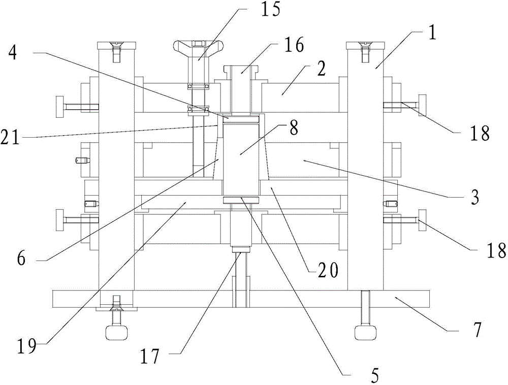
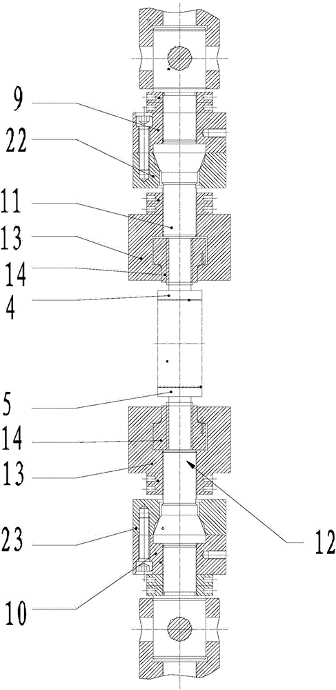
[0033] Such as figure 1 and figure 2 As shown, the rock axial tensile test device adopted in the present invention includes a column 1, an upper positioning sleeve 2, a lower positioning sleeve 3, an upper puller 4, a lower puller 5, a specimen clamping sleeve 6 and a base plate 7. The column 1 is fixedly installed on the base plate 7, the upper positioning sleeve 2 is connected with the column 1, and the upper positioning sleeve 2 can move along the axial direction of the column 1, the lower positioning sleeve 3 is connected with the column 1, and the lower positioning sleeve 3 can move along the axial direction of the column 1, the specimen clamping sleeve 6 is connected with the column 1, and the specimen clamping sleeve 6 can move along the axial direction of the column 1, the upper slider 4 and the upper positioning sleeve 2 Connected, the pull-down head 5 is connec...


PUM

PropertyMeasurementUnit
tensile strengthaaaaaaaaaa

Abstract

The invention provides a rock axial tension test device and a rock axial tension test device in the field of material mechanical tests. The invention provides a rock axial tension test device which has a simple structure and can be used for guaranteeing the complete axial alignment of a test piece and upper and lower pull heads in an adhesion process and can also be used for effectively eliminating an eccentric phenomenon in a tension test process. The rock axial tension test device comprises an upright post, an upper positioning sleeve, a lower positioning sleeve, an upper pull head, a lower pull head, a test piece clamping sleeve and a bottom plate, as well as a clamping element, the clamping element comprises an inner side face and an outer side face, the inner side face is cylindrical, the outer side face is a conical surface, a conical surface matched with the outer side face of the clamping element is arranged on the clamping sleeve, and the clamping element is located in the conical surface of the clamping sleeve. The rock axial tension test device provided by the invention is used for solving the eccentric problem of a rock test piece when being pulled, and the rock test piece is aligned in a process of clamping the rock test piece.

Description

technical field [0001] The invention relates to a rock axial tensile test device and a rock axial tensile test method, in particular to a rock axial tensile test device and a rock axial tensile test method in the field of material mechanics tests. Background technique [0002] Rocks are mostly subjected to compressive stress and less to tensile stress. Therefore, attention is paid to the state of compressive and shear stress, and the experimental research on rock mechanical properties mainly focuses on the mechanical response of rock under compressive stress, including uniaxial, biaxial and triaxial compression tests, etc.; There are relatively few studies on mechanical properties. However, the stress state in engineering rock mass is often very complex, some areas are in the state of compressive stress, but some areas are in the state of tensile stress or tensile shear stress. [0003] The most notable feature of rock materials is that the tensile strength is much smaller...

Claims


Application Information

Patent Timeline
Patent Type & Authority Applications(China)
IPC IPC(8): G01N3/08G01N3/04
Inventor 曾纪全张强勇徐务本
Owner CHINA HYDROELECTRIC ENGINEERING CONSULTING GROUP CHENGDU RESEARCH HYDROELECTRIC INVESTIGATION DESIGN AND INSTITUTE
Why Eureka
Try Eureka