Wiring device special for power measurement

A wiring device and power measurement technology, applied in the direction of the housing of the measurement device, etc., can solve the problems of the secondary side not being able to connect in time, missing wiring, and long wiring time.

Inactive Publication Date: 2015-05-06
HEBEI RAINSER ELECTRIC EQUIP
View PDF5 Cites 0 Cited by
  • Summary
  • Abstract
  • Description
  • Claims
  • Application Information

AI Technical Summary

Problems solved by technology

[0002] At present, in the known field of medium-voltage electricity metering, in order to ensure the accuracy of metering and the reliability of the connection, the metering output of the secondary side of the primary electrical equipment is mostly connected directly to the metering junction box (or watt-hour meter) in the metering box by metering cables. It is not allowed to add any other connection points in the middle; most of the metering cables are BVR soft copper plastic wires, and the terminals connected to the metering junction box must be hot tinned before the equipment leaves the factory, resulting in It is in an unprotected state; during the installation of electrical equipment, due to the relatively short power outage time of the power bureau, the primary side is often directly powered after the installation is completed, resulting in the secondary side not being able to connect with the metering junction box in time, causing the on-site personnel to be charged homework, increase the difficulty of homework
Secondly, due to the limitations of the outdoor environment, the professional level of on-site wiring personnel and the influence of many secondary lines, it is very easy to cause problems such as long wiring time and missed wiring, wrong wiring or phase-to-phase short circuit during the wiring process.
As a result, it will cause damage to the primary electrical equipment and affect the normal power consumption of users.

Method used


Image

  • Wiring device special for power measurement
  • Wiring device special for power measurement
  • Wiring device special for power measurement

Examples


Embodiment Construction

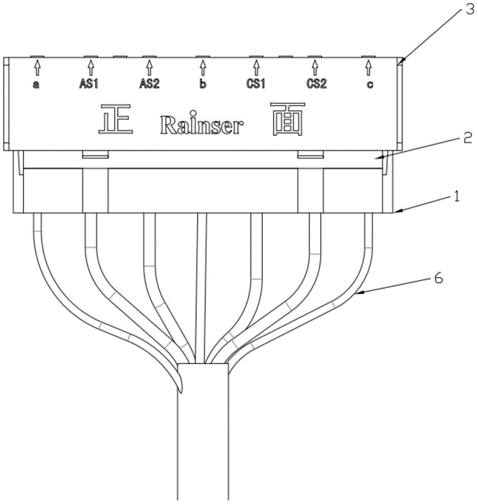
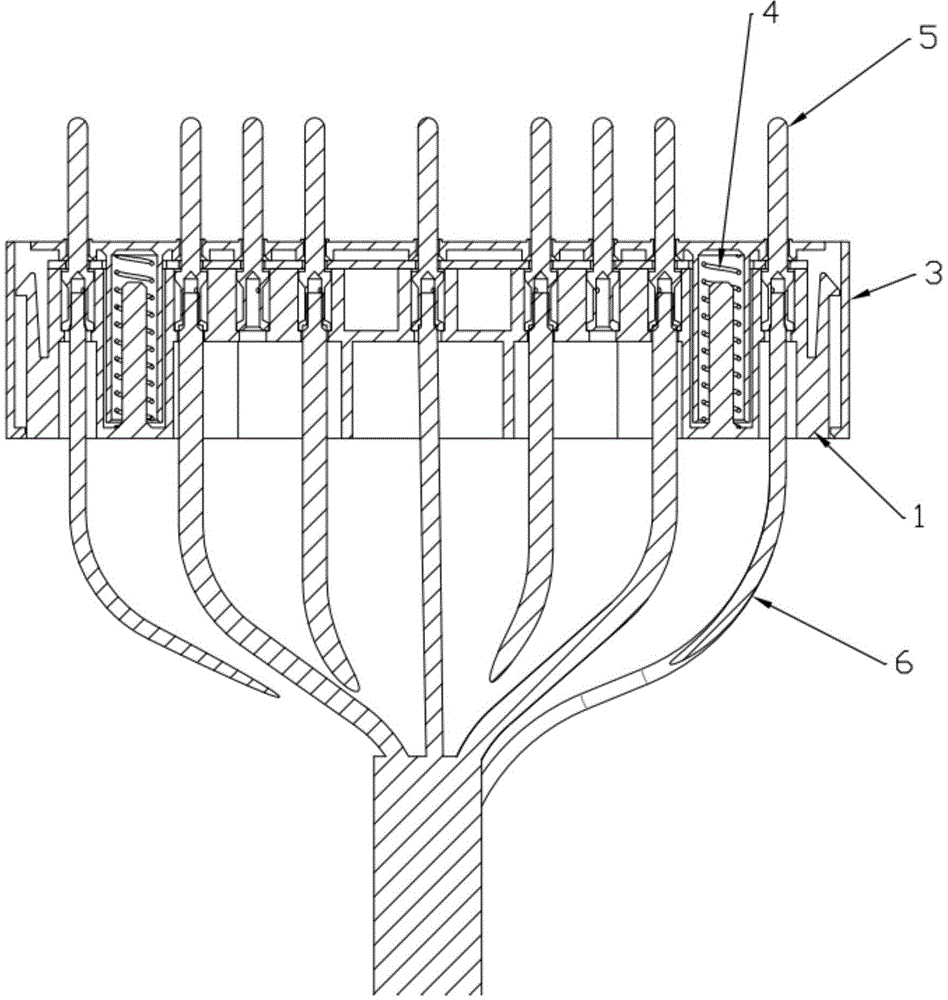
[0014] see figure 1 , a special wiring device for power metering in the figure, including a casing, a main body inserted into the casing, and several cold pressing pins fixed on the main body and protruding from the casing, the feature is: the main body is provided with several installation A cold-pressing needle chamber, the tail of the cold-pressing needle is placed in the cold-pressing needle chamber, and a cold-pressing needle hole corresponding to the cold-pressing needle chamber is provided on the shell, and the front part of the cold-pressing needle passes through the cold-pressing needle The crimping needle hole extends out of the shell; the rear part of the crimping needle chamber is provided with a threading hole, and the wire is inserted into the tail of the crimping needle through the threading hole;

[0015] A pressing plate is installed on the main body, and the pressing plate fixes the cold pressing needle on the main body, and a buckle structure is arranged bet...


PUM


Abstract

A wiring device special for power measurement comprises a shell, a main body and a plurality of cold pressing needles. The main body is inserted into the shell, the cold pressing needles are fixed on the main body and extend out of the shell, the main body is provided with a plurality of cold pressing needle mounting cavities, the tails of the cold pressing needles are disposed in the cold pressing needle mounting cavities, cold pressing needle holes corresponding to the cold pressing needle mounting cavities are formed in the shell, the front portions of the cold pressing needles penetrate out of the cold pressing needle holes to extend out of the shell, wire penetrating holes are formed in the rear portions of the cold pressing needle mounting cavities, leads are inserted into the tails of the cold pressing needles through the wire penetrating holes, wedge-shaped clamping heads are arranged on two sides of the main body, limiting bosses matched with the clamping heads are arranged on the inner surface of the shell, and supporting springs parallel to the cold pressing needles in direction are arranged between the shell and the main body. By the wiring device, mistaken wiring and missing wiring of operating personnel can be eliminated, the problem of short-out of equipment in the process of operation can be solved effectively, and exposed secondary wires can be effectively protected.

Description

technical field [0001] The invention relates to the technical field of electric wire connection, in particular to a special wiring device for electric power metering. Background technique [0002] At present, in the known field of medium-voltage electricity metering, in order to ensure the accuracy of metering and the reliability of the connection, the metering output of the secondary side of the primary electrical equipment is mostly connected directly to the metering junction box (or watt-hour meter) in the metering box by metering cables. It is not allowed to add any other connection points in the middle; most of the metering cables are BVR soft copper plastic wires, and the terminals connected to the metering junction box must be hot tinned before the equipment leaves the factory, resulting in It is in an unprotected state; during the installation of electrical equipment, due to the relatively short power outage time of the power bureau, the primary side is often directl...

Claims


Application Information

Patent Timeline
Patent Type & Authority Applications(China)
IPC IPC(8): G01R1/04
Inventor 田永志左伟伟高宏达
Owner HEBEI RAINSER ELECTRIC EQUIP
Why Eureka
Try Eureka