Supercharge Your Innovation With Domain-Expert AI Agents!

Direct-drive switch reluctance motor with teeth arranged at shaft end

A switched reluctance motor, direct drive technology, applied in the direction of electrical components, electromechanical devices, electric components, etc., can solve problems such as looseness, cable shedding, stringing, etc., to ensure service life, ensure accuracy, and solve corrosion problems Effect

Inactive Publication Date: 2015-05-06
淄博京科电气研究所
View PDF7 Cites 0 Cited by
  • Summary
  • Abstract
  • Description
  • Claims
  • Application Information

AI Technical Summary

Problems solved by technology

[0004] First, because the junction box and the cover have an outlet, it cannot be guaranteed that water mist and salt mist will not enter at all;
[0005] Second, the power cord is only fixed by the screw plate on the terminal, which is not firm enough to easily cause the cable to fall off from the terminal
[0006] Third, when the rotor of the switched reluctance motor rotates, it will be subjected to resistance or even collision force. These forces will first act on the gears on it, and the gears are fixed or even directly put on by the vault device. A long time will lead to loosening or stringing, which greatly affects the control accuracy of the switched reluctance motor

Method used


Image

  • Direct-drive switch reluctance motor with teeth arranged at shaft end
  • Direct-drive switch reluctance motor with teeth arranged at shaft end
  • Direct-drive switch reluctance motor with teeth arranged at shaft end

Examples


Embodiment 1

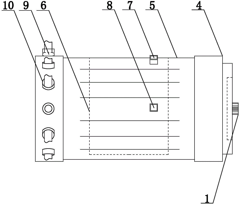
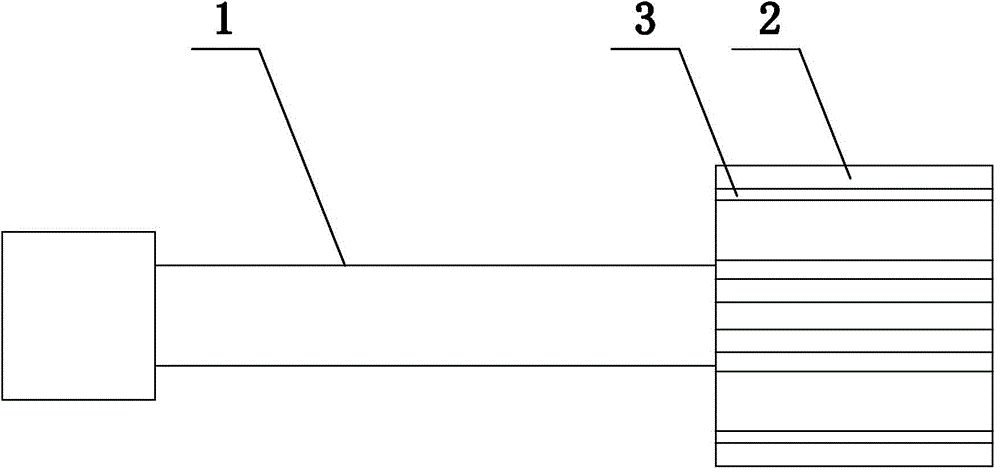
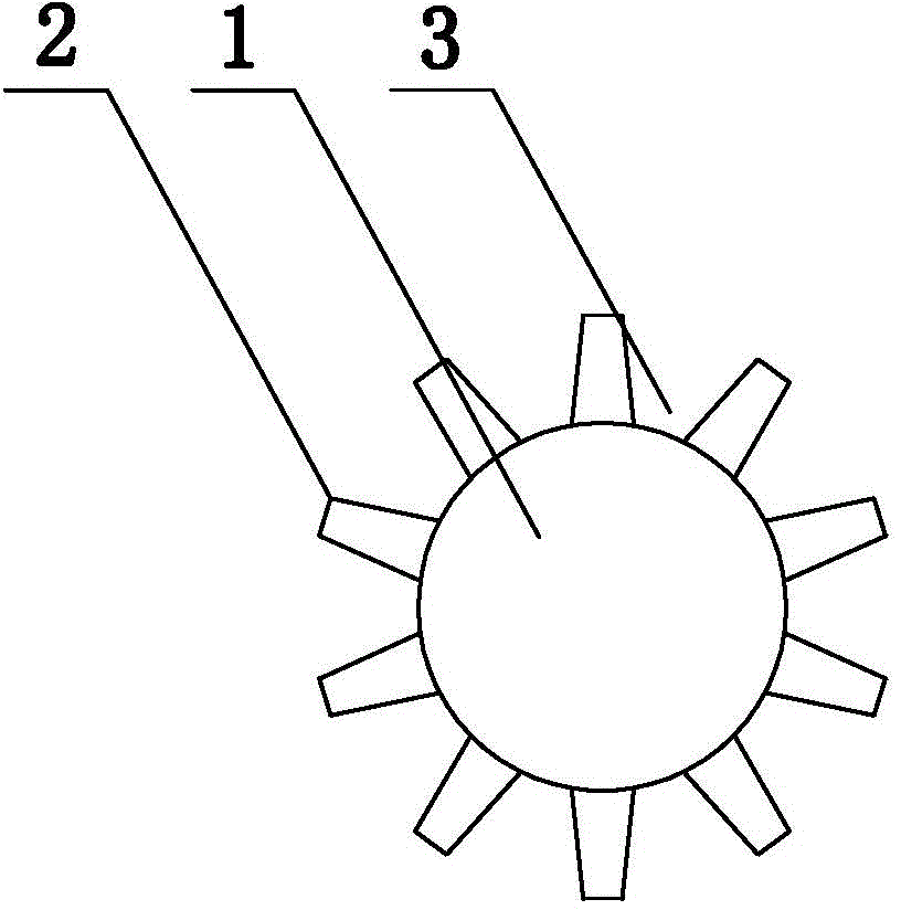
[0027] Embodiment 1: as figure 1 As shown, the shaft-end toothed direct drive switched reluctance motor of the present invention includes a switched reluctance motor 4, the switched reluctance motor 4 includes a rotating shaft 1, and an interlayer 6 is arranged in the shell 5 of the switched reluctance motor 4, and the shell 5 is provided with a water inlet 7 and a water outlet 8, and the interlayer 6 communicates with the outside world through the water inlet 7 and the water outlet 8. One end of the rotating shaft 1 is provided with a depression 2, and the depressions 2 are in a circular array based on the center of the cross-section of the rotating shaft 1. The protuberances between the two depressions 2 form teeth 3, and one side of the casing 5 of the switched reluctance motor 4 is provided with 6 connection ports 9, and the connection ports 9 are provided with threads, and are provided with a collar 10, and the collar 10 is set on the On the insulating skin of the cable, ...

Embodiment 2

[0028] Embodiment 2: On the basis of the structure described in Embodiment 1, the cross section of the depressions 2 is arc-shaped, and the shape and size of each depression 2 correspond to each other.

Embodiment 3

[0029] Embodiment 3: On the basis of the structure described in Embodiment 2, the teeth 3 are arc-shaped.


PUM


Abstract

The invention provides a direct-drive switch reluctance motor with teeth arranged at the shaft end and belongs to the field of switch reluctance motors. The direct-drive switch reluctance motor with teeth arranged at the shaft end includes a switch reluctance motor, wherein the switch reluctance motor is provided with a rotating shaft, and an interlayer is arranged in a casing of the switch reluctance motor. A water inlet and a water outlet are arranged on the casing, and the interlayer is communicated with the outside through the water inlet and the water outlet. The direct-drive switch reluctance motor with teeth arranged at the shaft end is characterized in that recesses are formed in one end of the rotating shaft and are arrayed in a circle around the circle center of the cross section of the rotating shaft, and upheavals between each two random recesses form teeth. Six wiring ports are arranged on one side of the casing, and threads are arranged in the wiring ports. Lantern rings are sleeved on insulation skins of cables, and threads are arranged on the outer portions of the lantern rings. The threads on the outer portions of the lantern rings are matched with the threads in the wiring ports, so the teeth on the rotating shaft do not loosen or shift, water and salt mist can be resisted effectively and the power lines are not apt to fall.

Description

technical field [0001] The invention provides a shaft-end toothed direct-drive switched reluctance motor, which belongs to the field of switched reluctance motors. Background technique [0002] When wiring the existing water-cooled switch side resistance motors, a junction box is often arranged on the casing, and a wiring terminal is arranged in the junction box. One end of the wiring terminal is connected to the stator, and the other end fixes the power cord. When the cover is closed, the power cord will come out from the outlet on the cover, so as to achieve the function of waterproof and anti-salt spray at the terminal; when the switched reluctance motor provides power, it needs to install a gear on its rotor with a fixing device , The rotor of the switched reluctance motor cooperates with other gears through the gears on it to make the corresponding parts of the equipment rotate. [0003] Current prior art defect is: [0004] First, because the junction box is equipped...

Claims


Application Information

Patent Timeline
Patent Type & Authority Applications(China)
IPC IPC(8): H02K5/22H02K5/10H02K7/10H02K7/116
CPCH02K7/003H02K5/225
Inventor 董义鹏李明贤郭源生李向阳石光峰
Owner 淄博京科电气研究所
Features
  • R&D
  • Intellectual Property
  • Life Sciences
  • Materials
  • Tech Scout
  • Unparalleled Data Quality
  • Higher Quality Content
  • 60% Fewer Hallucinations
Learn More