

Hollow motor
A hollow and hollow shaft technology, used in electrical components, electromechanical devices, electric components, etc., can solve the problems of unstable rotation speed, complex structure, stuck, etc., to reduce the loss of the transmission link, the transmission effect is good, and the stability is guaranteed. Effect
- Summary
- Abstract
- Description
- Claims
- Application Information
AI Technical Summary
Problems solved by technology
Method used
Image

Examples
Embodiment Construction
[0020] The technical solutions of the present invention will be further described below in conjunction with the accompanying drawings and through specific implementation methods.
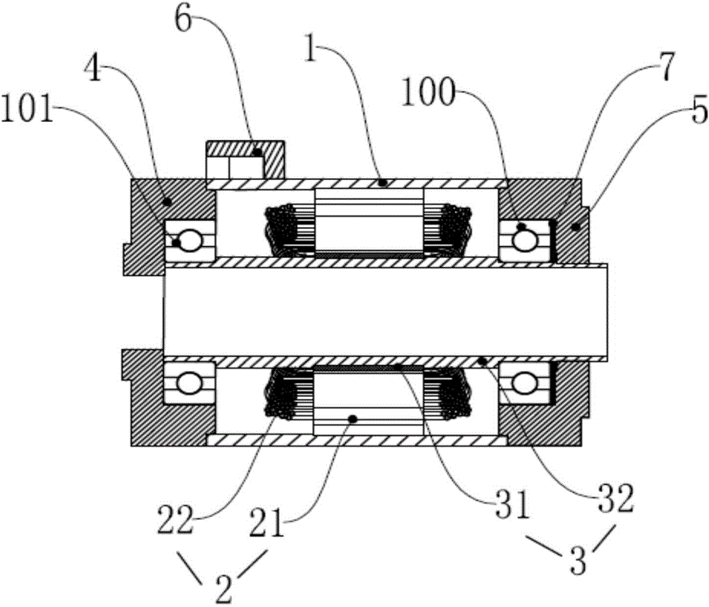
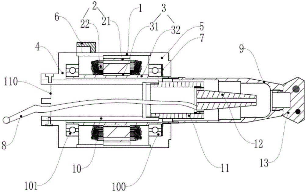
[0021] A hollow motor, comprising a shell 1, a stator assembly 2, a rotor assembly 3, a rear cover 4 and a front cover 5; the stator assembly 2 includes a bobbin 21 and a magnetic steel 22; the rotor assembly 3 includes a rotor shaft 31 and the hollow shaft 32, the hollow shaft 32 passes through and is fixed to the rotor shaft 31; the bobbin 21 is located between the rotor shaft 31 and the casing 1; the front cover 5 passes through the front The bearing 100 is connected with the front end of the hollow shaft 32 ; the rear cover 4 is connected with the rear end of the hollow shaft 32 through the rear bearing 101 .
[0022] The present invention can directly use the hollow shaft 32 to connect with the transmission structure, which can reduce the loss of the transmission link compared with the previous...
PUM
 Abstract
Description
Claims
Application Information