Heat dissipation device of air blower

A technology of a heat sink and a blower, which is applied to electromechanical devices, cooling/ventilation devices, components of a pumping device for elastic fluids, etc. Use flexible and convenient effects

Inactive Publication Date: 2015-05-06
NINGBO SHENGHONG MACHINERY EQUIP
View PDF4 Cites 1 Cited by
  • Summary
  • Abstract
  • Description
  • Claims
  • Application Information

AI Technical Summary

Problems solved by technology

Although the pressure of the blower is constant and the kinetic energy is sufficient, because the blower is often in a long-time working state, the long-term and hig

Method used


Image

  • Heat dissipation device of air blower
  • Heat dissipation device of air blower

Examples


Embodiment Construction

[0019] The following are specific embodiments of the present invention and in conjunction with the accompanying drawings, the technical solutions of the present invention are further described, but the present invention is not limited to these embodiments.

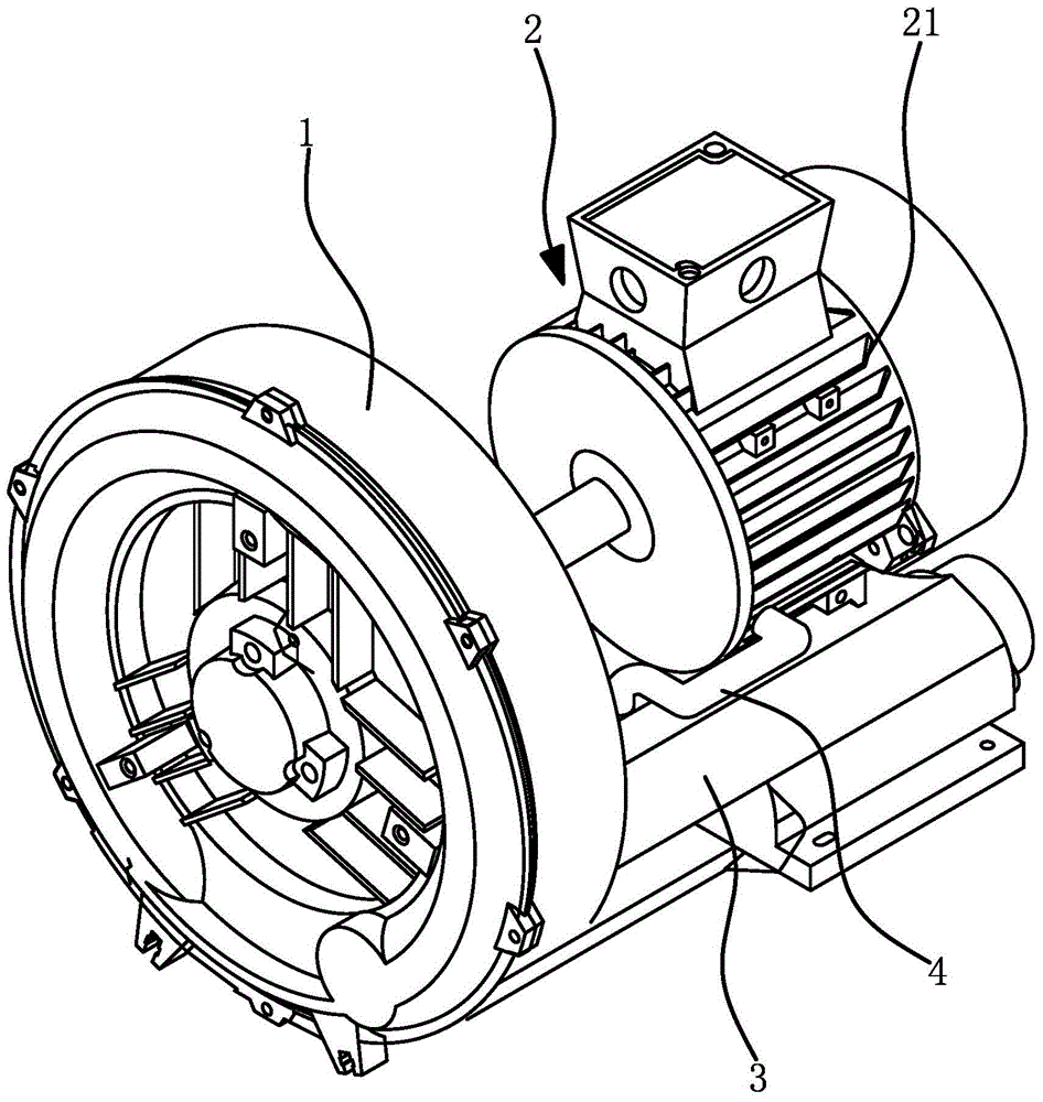
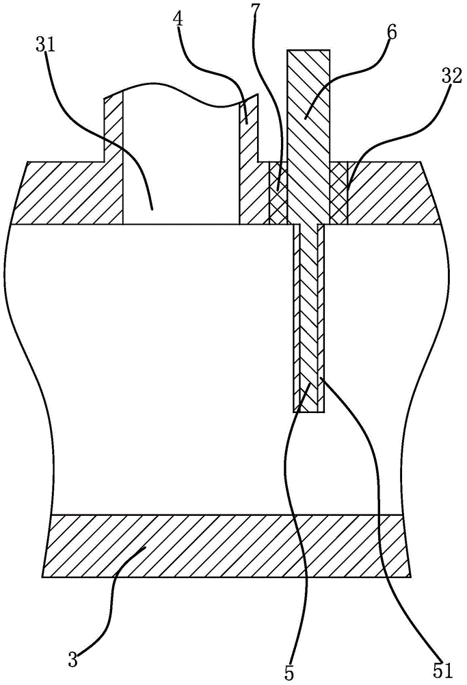
[0020] Such as figure 1 , figure 2 As shown, a heat dissipation device for a blower, the blower includes an air barrel 1 and a motor 2, the air barrel 1 and the motor 2 are fixedly connected on a base, the motor 2 has a motor casing 21, and components such as coils and motor 2 shafts are arranged on Inside the motor housing 21, the motor housing 21 is fixedly connected with the air barrel 1, and the air outlet pipe 3 is connected to the air barrel 1. The motor 2 drives the fan blades in the air barrel 1 to rotate to generate air flow, and the air flow passes through the air outlet pipe 3 Exhaust, a branch pipe 4 is fixedly connected to the air outlet pipe 3, one end of the branch pipe 4 is connected with the air outlet p...


PUM


Abstract

The invention provides a heat dissipation device of an air blower and belongs to the technical field of fan devices. The problem that a motor of an existing air blower difficultly and effectively dissipates heat is solved. The air blower comprises an air barrel and a motor, wherein the motor is provided with a motor housing, the motor housing is fixedly connected with the air barrel, an air outlet pipe is connected to the air barrel, a branch pipe is fixedly connected to the air outlet pipe, one end of the branch pipe is communicated with the air outlet pipe, the other end of the branch pipe is communicated with the inner cavity of the motor housing, and a flow guide plate is rotatably connected in the air outlet pipe and is connected with an adjusting part. The heat dissipation device of the air blower can conduct timely and moderate heat dissipation and temperature reduction on the motor and is convenient to use.

Description

technical field [0001] The invention belongs to the technical field of blower equipment, and relates to a cooling device for a blower. Background technique [0002] The blower is mainly composed of motor, air filter, impeller, air chamber, base and other components. The air is sucked, compressed and discharged by the volume change between the blades. Since the impeller runs without friction in the body and does not need lubrication, the discharge The gas does not contain oil, and it is an ideal source of pneumatic conveying gas for chemical, food and other industries. When in use, with the change of pressure, the change of flow rate is very small, but the flow rate changes with the speed, so the selection range of pressure is very wide, and the choice of flow rate can meet the needs by selecting the speed. There are various types of blowers, which can be divided into Lu-type blowers, high-pressure blowers, etc. Among them, high-pressure blowers, also called high-pressure bl...

Claims


Application Information

Patent Timeline
IPC IPC(8): H02K9/16H02K5/18
CPCF04D29/5806F04D29/582H02K9/06Y02E10/72
Inventor 陈镇华周政富
Owner NINGBO SHENGHONG MACHINERY EQUIP
Why Eureka
Try Eureka