
A servo motor stator and rotor assembly tooling

A technology for assembling tooling and servo motors, applied in electromechanical devices, manufacturing motor generators, electrical components, etc., can solve the problems of low assembly efficiency of stators and rotors, and achieve the effect of simple motor assembly process, convenient inspection, and improved efficiency

Active Publication Date: 2018-03-09
NINGBO PHASE MOTION CONTROL
View PDF4 Cites 0 Cited by
  • Summary
  • Abstract
  • Description
  • Claims
  • Application Information

AI Technical Summary

Problems solved by technology

[0004] The technical problem to be solved by the present invention is to provide a servo motor stator and rotor assembly tool to solve the problem of low assembly efficiency of the existing stator and rotor

Method used


Image

  • A servo motor stator and rotor assembly tooling
  • A servo motor stator and rotor assembly tooling

Examples


Embodiment 1

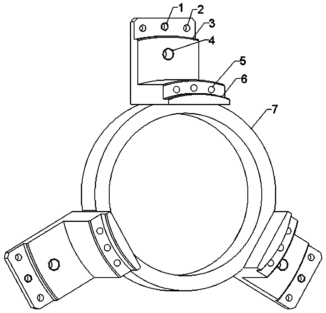
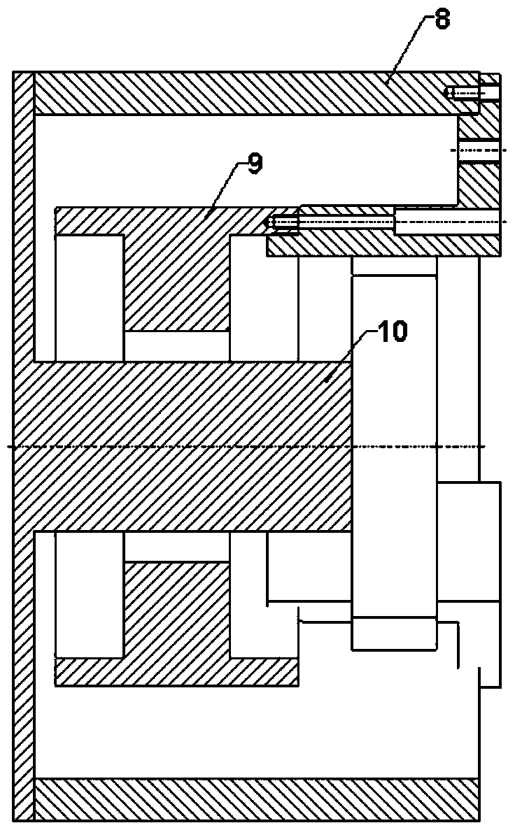
[0014] like Figure 1 ~ Figure 2 As shown, a stator-rotor assembly tooling is composed of an external connection structure, which is a three-block structure in this example, and an internal ring structure. This mechanism includes outer ring stator positioning hole 2, outer ring arc notch groove 3, inner ring fixed rotor positioning hole 5, inner ring arc notch groove 6, retraction threaded hole 1, hoisting hole 4, tooling support ring 7 . Use the positioning hole 2, the circular arc groove 3 of the outer ring to cooperate with the stator 8, the fixed rotor positioning hole 5 of the inner ring and the circular arc groove 6 of the inner ring to cooperate with the rotor 9, and the retreat threaded hole 1 is used when the tooling is disassembled. The hoisting hole 4 is used when lifting the motor or tooling, and the support ring 7 is used when the rotating shaft 10 and the rotor 9 are assembled.

[0015] During the assembly process of the stator and rotor, first use screws to lo...


PUM


Abstract

The invention relates to a stator and rotor assembly tool for a servo motor, which includes a support ring, which is a circular ring, and three positioning blocks are installed on the support ring with equal arcs. There is a positioning hole for the outer ring stator on each of the right sides, and a retreat threaded hole is opened on the positioning block between the positioning holes of the outer ring stator. There are hoisting holes on the platform, three inner ring fixed rotor positioning holes are opened on the upper surface of the positioning block, and the upper end surface of the positioning block is protruding upward from the side close to the axis line of the support ring to form a non-stop groove . The invention makes the motor assembly process easier, can effectively control the assembly gap of the stator and rotor, facilitates the inspection of the gap, and improves the efficiency of the stator and rotor assembly; it can conveniently assemble the motor to the equipment port, and it is easier to disassemble the motor. The control of the stator and rotor clearance on the equipment plays a positive guiding role.

Description

technical field [0001] The invention belongs to the technical field of motor tooling, in particular to a servo motor stator and rotor assembly tooling. Background technique [0002] For direct drive servo motors, the assembly of the stator and rotor requires the guidance of special working parts, and the gap between the stator and rotor is not easy to control. When the motor is installed on the equipment port, due to the strong magnetic force between the stator and rotor, it is difficult to install and disassemble the motor stator and rotor on the equipment. [0003] During the assembly process of the stator and rotor of this type of motor, if the operation is improper, the stator and rotor are very easy to absorb, which may cause damage to the magnetic steel or cause safety hazards, which seriously affects the assembly efficiency of this type of motor. When this type of motor is assembled to the equipment port, the motor stator needs to be fixed on the equipment port, and ...

Claims


Application Information

Patent Timeline
Patent Type & Authority Patents(China)
IPC IPC(8): H02K15/00
Inventor 朱法龙周丹阿力牛正蕊
Owner NINGBO PHASE MOTION CONTROL
Learn More