Airborne composite material profile accurate molding deformation compensation method

A composite material and deformation compensation technology, which is applied in the field of aircraft composite material surface precision molding deformation compensation, can solve the problems of inability to form batches, failure to obtain deformation rules, and decreased accuracy.

Active Publication Date: 2015-05-13
哈尔滨新科锐工艺装备制造有限公司 +1
View PDF2 Cites 18 Cited by
  • Summary
  • Abstract
  • Description
  • Claims
  • Application Information

AI Technical Summary

Problems solved by technology

This method has certain defects, that is, in the process of composite material molding, due to the difference in thermal expansion coefficient between the mold material and the composite material part, there is a certain degree of error between the profile of the composite material part after molding and the model surface of the original part number. , the size is deformed, the design requirements cannot be met, the accuracy is reduced, and the use of the parts is affected, especially in the use of composite material surface parts of the aircraft. The parts of the aircraft are produced in a single large piece and cannot be formed into a certain batch. Quantity, resulting in the inability to obtain the deformation laws of different parts of the composite material, the number of the entire profile of the aircraft is too large and the shape is different, resulting in the inability to use the entire profile of the aircraft as a test piece, because the cost is too high
[0003] The present invention proposes a method for compensating the deformation of composite material profiles for aircrafts. The patent retrieval using the keyword "precise molding" yields 1 invention patent, and the patent retrieval using the keyword "deformation compensation" has no relevant patents, and none have been found. Patents related to "Precise Forming Deformation Compensation Method for Composite Materials"

Method used


Image

  • Airborne composite material profile accurate molding deformation compensation method
  • Airborne composite material profile accurate molding deformation compensation method
  • Airborne composite material profile accurate molding deformation compensation method

Examples


Embodiment Construction

[0027] The technical solution can also be realized through the following technical measures and the present invention will be further described below in conjunction with the accompanying drawings:

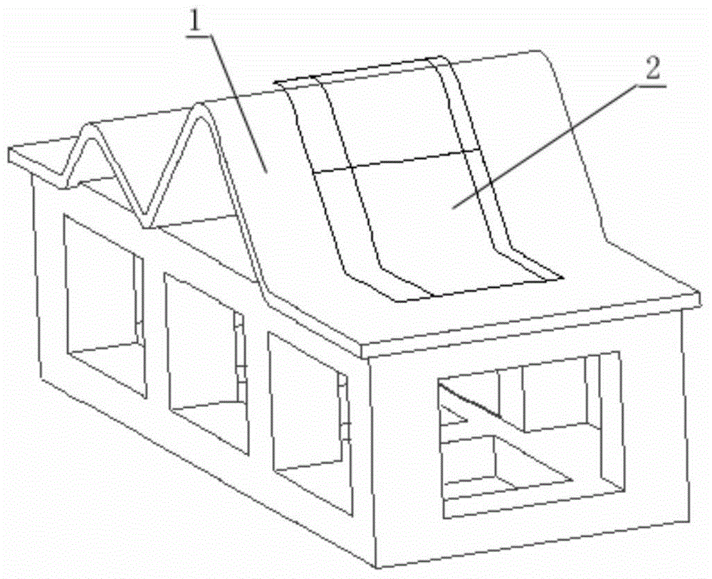
[0028] The present invention is based on the CATIA platform, and takes a specific compensation calculation of composite material surface as an example to illustrate how to correct and calculate the model surface according to the number of composite material parts, and compensate the deformation in the molding process to obtain the mold surface Methods.

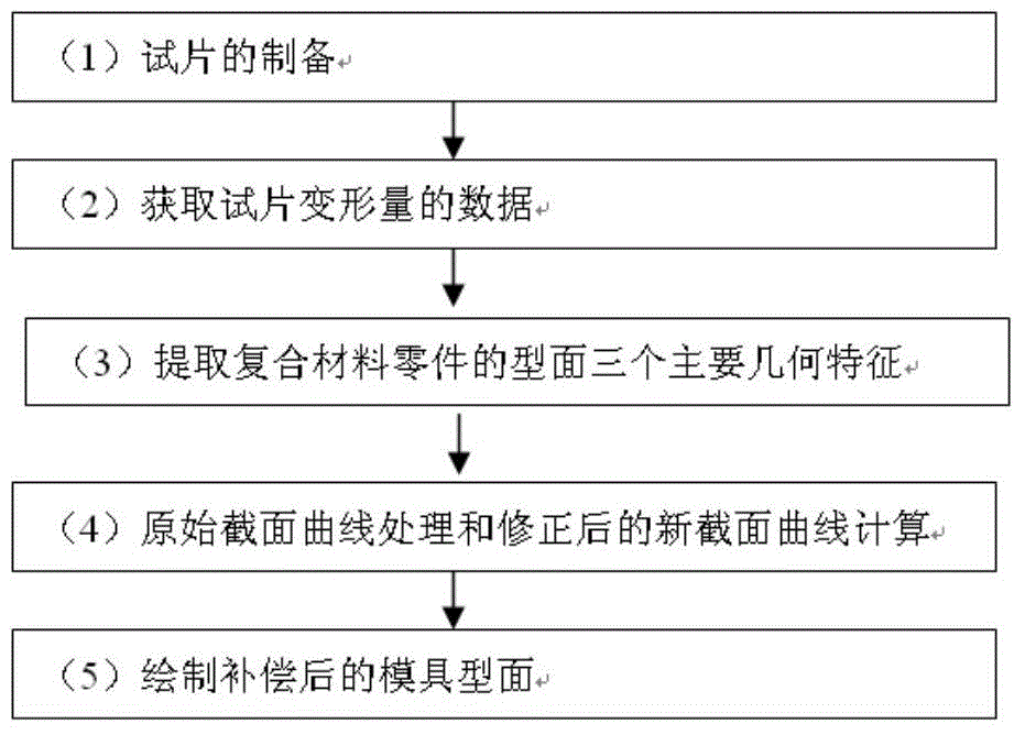
[0029] figure 1 It is a flow chart of the precision forming deformation compensation method of the present invention, and the main steps of the method are as follows:

[0030] (1) The preparation of the test piece, according to the structure and characteristics of different profiles of the composite material parts and the original data of the model surface of the number of parts, select a suitable area on the special mold for test...


PUM


Abstract

The invention provides an airborne composite material profile accurate molding deformation compensation method. Aiming at the condition that the composite material molding method generally adopts a thermal molding method for manufacturing a die profile by using a profile the same as a composite material product data model, and the profile precision is reduced since the deformation rule of the profile for the single and large aircraft composite material cannot be obtained, the invention provides the airborne composite material profile accurate molding deformation compensation method. The method comprises the following steps: using the profile of the part data model as original data, manufacturing a test-piece and measuring according to data model geometric characteristic, establishing a test-piece deformation database, amending and compensating an original section curve to obtain an amended section curve, and acquiring an amended molding surface by using three-dimensional CATIA software, using the amended molding surface as a molding face for manufacturing the die, and then manufacturing a composite material product; therefore, the precision of the composite material product is greatly improved, the quality of the composite material profile is improved, and the production cost is reduced.

Description

technical field [0001] The invention relates to a method for compensating the deformation of a composite material profile accurately formed for an aircraft. Background technique [0002] At present, most of the molding methods of composite parts use autoclave curing molding. The selection of mold materials and the manufacturing accuracy of mold surfaces directly affect the accuracy of composite parts. The composite material mold surface is usually determined according to the composite material part surface, and the same surface is used for mold manufacturing. This method has certain defects, that is, in the process of composite material molding, due to the difference in thermal expansion coefficient between the mold material and the composite material part, there is a certain degree of error between the profile of the composite material part after molding and the model surface of the original part number. , the size is deformed, the design requirements cannot be met, the ac...

Claims


Application Information

Patent Timeline
Patent Type & Authority Applications(China)
IPC IPC(8): B29C70/54
CPCB29C70/54
Inventor 徐英杰韩志仁吴子斌刘宝明刘建波林明王青张德生徐褔泉丁志德扈心建张力安周立忠蒋世英王义双杨长兵赵鑫王喜孙龙吴继超张颜龙姜涛
Owner 哈尔滨新科锐工艺装备制造有限公司
Why Eureka
Try Eureka