
Vehicle and its subframe mounting point structure

A sub-frame, mounting point technology, applied in the substructure, vehicle components, transportation and packaging, etc., can solve the problems affecting the rigidity and strength of the sub-frame body

Inactive Publication Date: 2017-04-19
SAIC MOTOR
View PDF7 Cites 0 Cited by
  • Summary
  • Abstract
  • Description
  • Claims
  • Application Information

AI Technical Summary

Problems solved by technology

Or through the large deformation of the sub-frame body to achieve energy absorption, and these two methods may affect the stiffness and strength of the sub-frame body

Method used


Image

  • Vehicle and its subframe mounting point structure
  • Vehicle and its subframe mounting point structure
  • Vehicle and its subframe mounting point structure

Examples


Embodiment Construction

[0026] In order to help those skilled in the art to accurately understand the claimed subject matter of the present invention, the specific implementation manners of the present invention will be described in detail below in conjunction with the accompanying drawings.

[0027] see figure 1 , is a schematic diagram of the subframe mounting point structure involved in the present invention. The structure is a bolt sleeve structure, used between the subframe and the body to connect the two. When the subframe is under load, the bolts transmit force to the bolt sleeve, and the bolt sleeve transmits force to the body mounting plate, thereby tearing the body and pulling the sleeve out of the body.

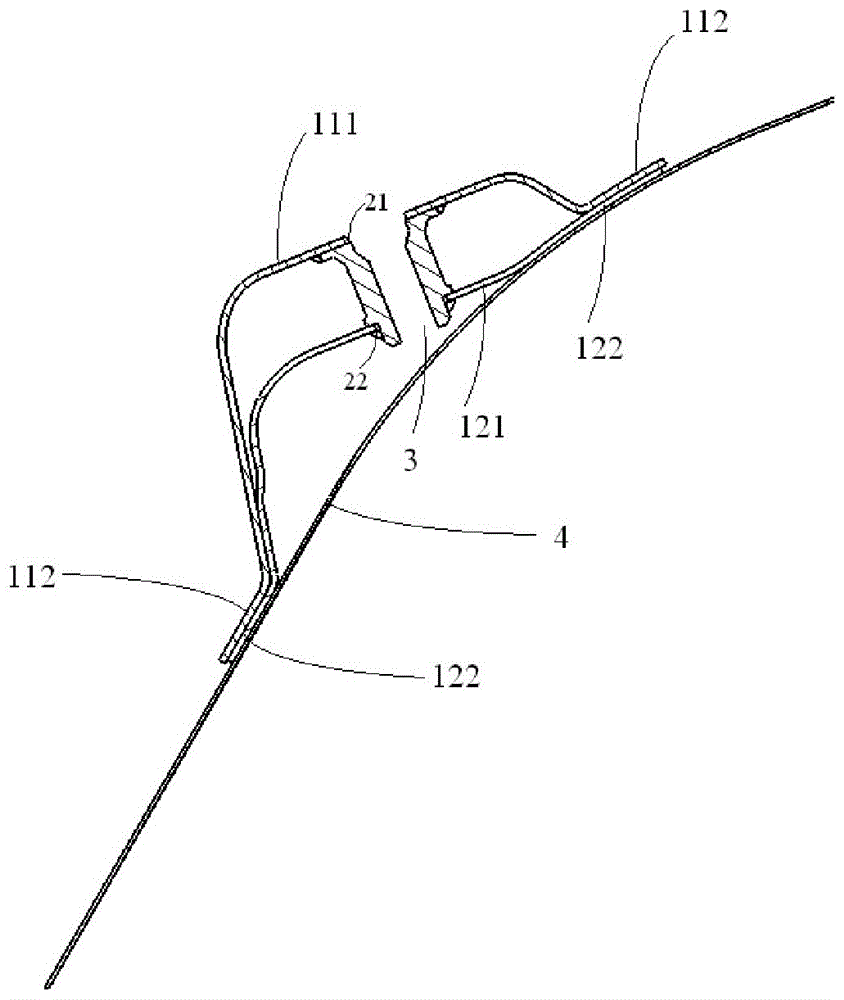
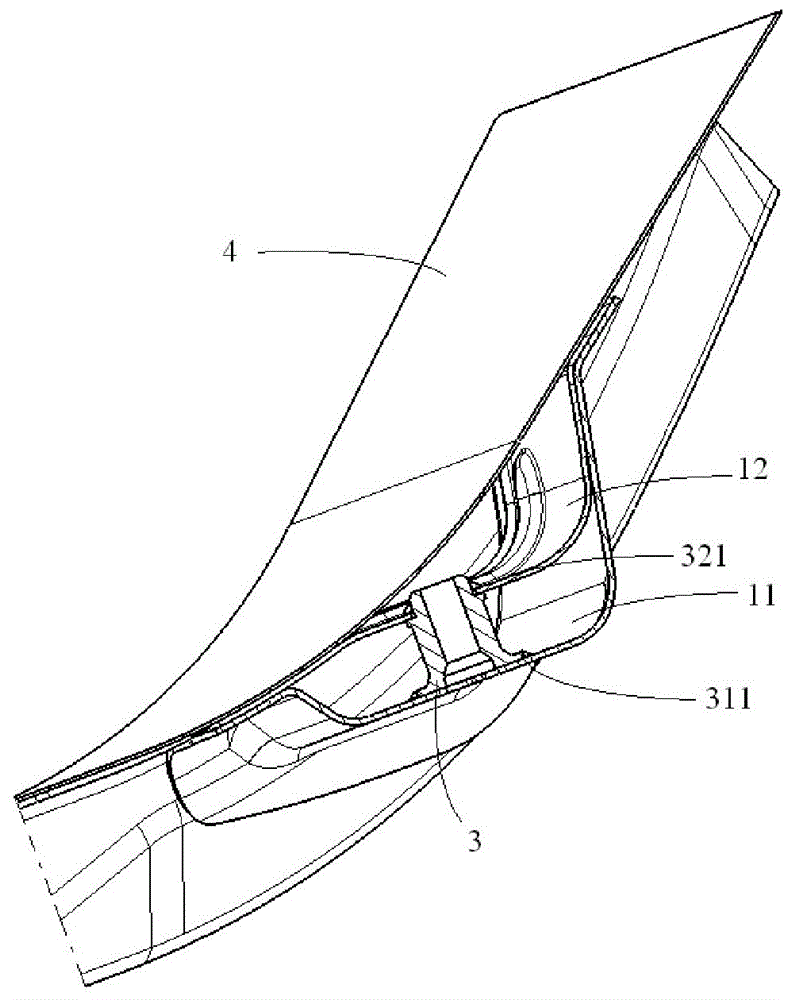
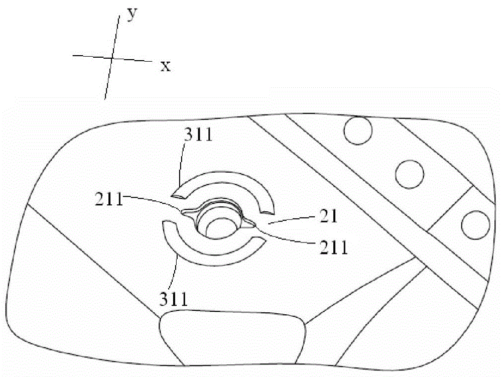
[0028] see figure 2 -4 is a schematic diagram of the subframe installation point structure involved in the present invention, wherein figure 2 It is a schematic diagram of the initial state after the assembly of the subframe and the body, image 3 It is a schematic cross-section alo...


PUM


Abstract

The invention discloses an auxiliary frame installing point structure. The auxiliary frame installing point structure comprises a reinforcing structure, a first disengagement groove and a sleeve. The reinforcing structure comprises a first reinforcing plate for being fixed to a vehicle body. The first disengagement groove is formed in the first reinforcing plate and has a first direction, and the first direction is identical with the predicted direction of collision force resultant force received by an auxiliary frame. The sleeve is arranged in the first disengagement groove, threads for being connected with the auxiliary frame are arranged in the sleeve, and the sleeve and the first reinforcing plate are fixed. When impacted, the auxiliary frame can be quickly and reliably disengaged from the vehicle body, and safety is improved.

Description

technical field [0001] The invention relates to a vehicle frame structure, in particular to a sub-frame mounting point structure. [0002] The present invention also relates to a vehicle comprising the above-mentioned subframe mounting point structure. Background technique [0003] At present, the connection between the front half of the sub-frame and the body is divided into two types: soft connection and hard connection. The soft connection is to connect the sub-frame and the body through a flexible bushing material, while the hard connection is directly through bolts and bolt sleeves. Tubes and the like directly fix the subframe on the vehicle body. Generally speaking, during a frontal collision of a vehicle, the semi-subframe will have an impact when it touches the powertrain. If the impact force is not effectively released, it will be transmitted to the passenger compartment, resulting in a large acceleration. When the impact force is large enough, the softly connecte...

Claims


Application Information

Patent Timeline
Patent Type & Authority Patents(China)
IPC IPC(8): B62D21/09B62D21/15
CPCB62D21/09B62D21/15
Inventor 午利民臧宏建杨志刚李政张金萍张鹏刘勇孙成智戴轶王光耀
Owner SAIC MOTOR
Learn More