Automatic pipe feeding device of sealing machine

A sealing machine and automatic technology, which is applied in the direction of conveyor objects, transportation and packaging, etc., can solve the problems that the filament cannot be guaranteed to enter the hole, the manipulator has a large range of motion, and the success rate of clamping the stem is low, and the loading and unloading time is short. , fewer mechanical actions, and easy maintenance

Inactive Publication Date: 2015-05-13
家雄灯饰(濮阳)有限公司
View PDF6 Cites 1 Cited by
  • Summary
  • Abstract
  • Description
  • Claims
  • Application Information

AI Technical Summary

Problems solved by technology

[0002] The patent application with the Chinese patent publication number CN203644722U discloses a lamp tube stem conveyor. The unloading manipulator is composed of two parallel movable claws to form two stem positions, which are docked with the conveying rail to finally send the stem into the sealing machine. The two translational slide rails can drive the two movable claws to move the stem back and forth between the discharge end of the conveying rail and the sealing machine; however, since the stems on the conveying rail slide down by gravity, the distance between the stems is relatively close, causing the manipulator to The success rate of clamping the stem is low, the movement range of the manipulator is large, and it takes a long time to load the tube, and because the hole of the sealing machine is small, it is impossible to ensure that the filament enters the hole, thus affecting the sealing effect

Method used


Image

  • Automatic pipe feeding device of sealing machine
  • Automatic pipe feeding device of sealing machine
  • Automatic pipe feeding device of sealing machine

Examples


Embodiment Construction

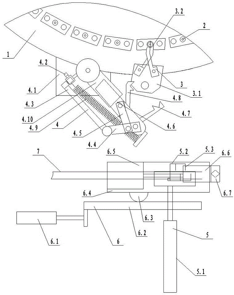
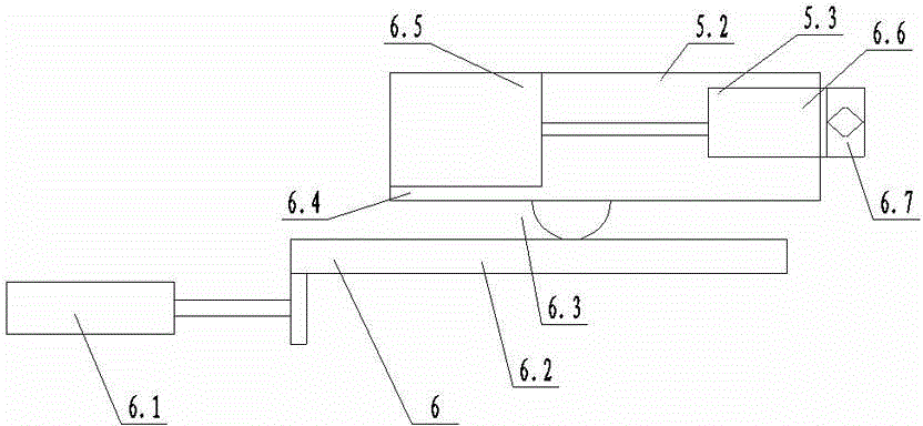
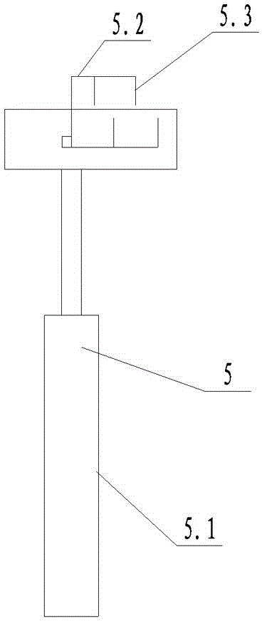
[0015] The automatic tube loading device of the sealing machine includes a stem separating device 5, a first transferring device 6, a second transferring device 4 and a stem guiding device 3, the stem separating device 5 includes a first telescopic device 5.1, and the first telescopic device 5.1 The piston rod is connected to the blocking rod, and the blocking rod is divided into two vertical rods 5.4. The top of the vertical rod 5.4 is connected to the cross rod 5.2. The gear teeth 5.3 are relatively staggered, and there is a gap between the front ends of the gear teeth 5.3 on the two crossbars 5.2. When the gear teeth 5.3 move forward and backward, only one stem moves forward through the gap, thereby separating the stem The effect of opening a certain interval.

[0016] The stem guide device 3 includes a guide base 3.1, and a guide fixture 3.2 is arranged on the guide base 3.1. When the guide fixture 3.2 is clamped, it is funnel-shaped. The guide fixture 3.2 can be driven me...


PUM


Abstract

The invention relates to energy-saving lamp production equipment, in particular to an automatic pipe feeding device of a sealing machine. The automatic pipe feeding device of the sealing machine comprises a stem separating device, a first transfer device, a second transfer device and a stem guide device. The stem separating device comprises a first telescopic device, a piston rod of the first telescopic device is connected with a blocking rod, the blocking rod is divided into two vertical rods, transverse rods are connected with the top ends of the vertical rods, a plurality of blocking teeth are arranged on the transverse rods, and the blocking teeth on the two transverse rods are oppositely staggered. The stem guide device comprises a guide base, a guide clamp is arranged on the guide base and is in a funnel shape in the clamping state, and hydraulic drive, pneumatic drive, electrical drive and mechanical drive can be adopted for the guide clamp. By means of the automatic pipe feeding device of the sealing machine, the successful rate of clamping stems by a mechanical arm is high, the phenomenon that filaments of the stems cannot enter holes can be avoided, and the feeding accuracy is improved and is high; the stems can be continuously fed, mechanical movements are few, the feeding and discharging time is short, efficiency is high, and maintenance is convenient.

Description

technical field [0001] The invention relates to an energy-saving lamp production equipment, in particular to an automatic tube loading device for a sealing machine. Background technique [0002] The patent application with the Chinese patent publication number CN203644722U discloses a lamp tube stem conveyor. The unloading manipulator is composed of two parallel movable claws to form two stem positions, which are docked with the conveying rail to finally send the stem into the sealing machine. The two translational slide rails can drive the two movable claws to move the stem back and forth between the discharge end of the conveying rail and the sealing machine; however, since the stems on the conveying rail slide down by gravity, the distance between the stems is relatively close, causing the manipulator to The success rate of clamping the stem is low, the movement range of the manipulator is large, and it takes a long time to load the tube, and because the hole of the seali...

Claims


Application Information

Patent Timeline
Patent Type & Authority Applications(China)
IPC IPC(8): B65G47/90
Inventor 杨平和
Owner 家雄灯饰(濮阳)有限公司
Why Eureka
Try Eureka