Quick pushing and transverse moving method for integral frame bridge

A frame bridge and jacking technology, which is applied in erecting/assembling bridges, bridges, bridge construction, etc., can solve the problems of long detour transition time period, inability to ensure the personal safety of maintenance personnel, and failure of common girder bridge schemes, etc., so as to reduce construction The effect of engineering quantity and construction protection quantity, reducing the safety risk of construction operation, and reducing the workload of operation and maintenance

Active Publication Date: 2015-05-13
CHINA RAILWAY SIYUAN SURVEY & DESIGN GRP
View PDF8 Cites 7 Cited by
  • Summary
  • Abstract
  • Description
  • Claims
  • Application Information

AI Technical Summary

Problems solved by technology

[0010] Iron-span iron or highway-span iron overpass generally adopts simply supported beams, continuous beams, frame bridges, rigid frame bridges and other forms. Under special conditions, channel beams and steel beams are also used. When the net height is strictly limited and only meets the minimum clear height requirements for passage (especially when the clear height only meets the minimum clearance height requirements for electrified railways), the prestressed concrete girder bridge has a high structural height and cannot meet the minimum passage under the bridge. Although the steel girder or section steel girder has a low structural height, when the existing railway across is an electrified railway, since the catenary, catenary catenary cables and return lines are all high-voltage electrified bodies, they are close to the contact Electromagnetic induction will occur on the steel girders or shaped steel girders set above the net bearing cables and the return line, which does not meet the requirements of safety, environmental protection, and energy saving, and can

Method used


Image

  • Quick pushing and transverse moving method for integral frame bridge
  • Quick pushing and transverse moving method for integral frame bridge
  • Quick pushing and transverse moving method for integral frame bridge

Examples


Embodiment Construction

[0049] The present invention will be further described in detail below in conjunction with the accompanying drawings and specific embodiments.

[0050] The frame bridge overall fast pushing lateral movement method of the present embodiment comprises the following steps:

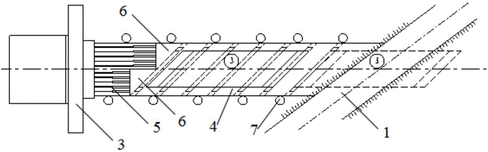
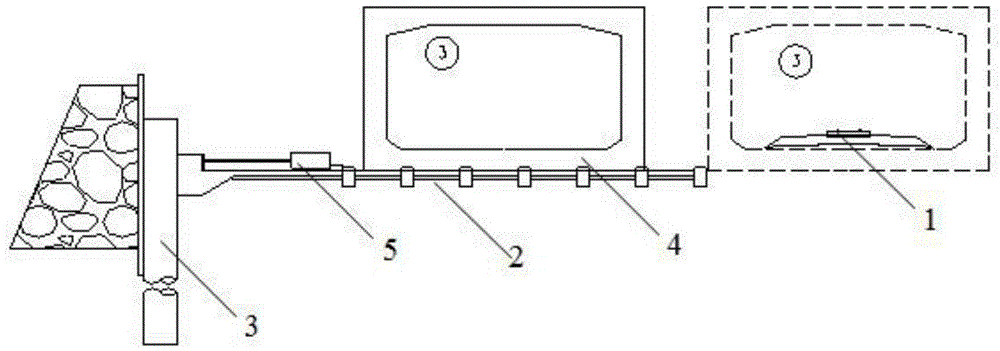
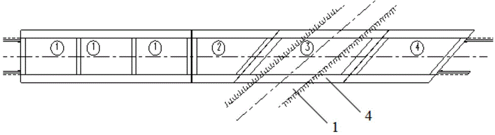
[0051] Construct the foundation pit on the side of the existing railway 1, such as Figure 1-2 As shown, the construction slide plate 2 and the hole-digging pile are constructed in the foundation pit, and the hole-digging pile is used as the pushing back 3, and the pile of digging is also provided with rubble stones behind it. After the lubricating isolation layer is set on the slide plate 2, the frame bridge 4 is prefabricated, and the top of the bottom plate of the frame bridge 4 is basically flush with the shoulder of the existing railway 1. In order to avoid "head-tying", the front end of the frame bridge is provided with a bow slope, and the slide plate 2 is provided with an upward slope along the direc...


PUM


Abstract

The invention discloses a quick pushing and transverse moving method for an integral frame bridge in existing rail way reconstruction, and a rail penetrates through the frame bridge. The method is characterized by comprising the steps that a sliding plate is constructed on one side of an existing rail way and a pushing back is constructed on the end of the sliding plate, the frame bridge is prefabricated on the sliding plate, and the top of a bottom plate of the frame bridge is roughly flush with the shoulder of the rail way; the pipe laying depth of pipelines on the two sides of a pushing and transverse moving area of the existing rail way is increased, and the pipe laying depth is larger than the bottom of the bottom plate of the frame bridge; a jack is installed at the back end of the frame bridge, lines and pathways of the existing rail way are dismantled, and the jack pushes and transversely moves the frame bridge; after the frame bridge is pushed and transversely moved to the position where an original rail way is removed, the lines and pathways of the existing rail way are restored in the normal position in the frame bridge. By the adoption of the form of the frame bridge, so the height of a bridge structure spanning the rail way is minimized, and a steel beam or a profiled-steel beam with the structure height in the same size is avoided; later operation and maintenance workloads of the rail way are lightened, and the requirements for safety, environment friendliness and energy conservation are satisfied.

Description

technical field [0001] The invention relates to the technical field of bridge construction, in particular to a method for rapid pushing and lateral movement of a frame bridge as a whole. Background technique [0002] When crossing the railway, the newly-built railway cross-rail or highway cross-rail interchange usually hopes that the clear height of the crossing should be as small as possible, so as to create better conditions for the horizontal and vertical section of the line; Section control, the height of the bridge structure across the railway and the clear height under the bridge are often strictly limited, and even have to be compressed to the limit. [0003] At present, the newly-built railway cross-rail or highway cross-rail interchanges have the following things in common: [0004] The height of the bridge structure across the railway; [0005] The clear height under the bridge crossing the railway, especially after considering the height of the construction supp...

Claims


Application Information

Patent Timeline
IPC IPC(8): E01D21/00
CPCE01D21/00
Inventor 刘智春贾伦学鲁丽娟饶少臣罗世东金福海
Owner CHINA RAILWAY SIYUAN SURVEY & DESIGN GRP
Why Eureka
Try Eureka