
Splash-proof labor-saving drilling fluid screening device

A screening device, labor-saving technology, applied in the direction of filtration and separation, flushing wellbore, earthwork drilling and mining, etc., can solve the problems of high energy consumption, low screening efficiency, inconvenient operation of filtration equipment, etc., to achieve improved filtration efficiency and convenience Replacement and cleaning, the effect of reducing energy consumption

Inactive Publication Date: 2015-05-13
CHENGDU KESHENG PETROLEUM TECH
View PDF14 Cites 1 Cited by
  • Summary
  • Abstract
  • Description
  • Claims
  • Application Information

AI Technical Summary

Problems solved by technology

[0005] The purpose of the present invention is to solve the problems of high energy consumption, low screening efficiency and inconvenient operation of the filtering equipment for drilling fluid solid phase control in the prior art, and provide a splash-proof and labor-saving drilling fluid screening device that solves the above problems

Method used


Image

  • Splash-proof labor-saving drilling fluid screening device
  • Splash-proof labor-saving drilling fluid screening device
  • Splash-proof labor-saving drilling fluid screening device

Examples


Embodiment 1

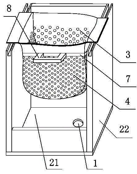
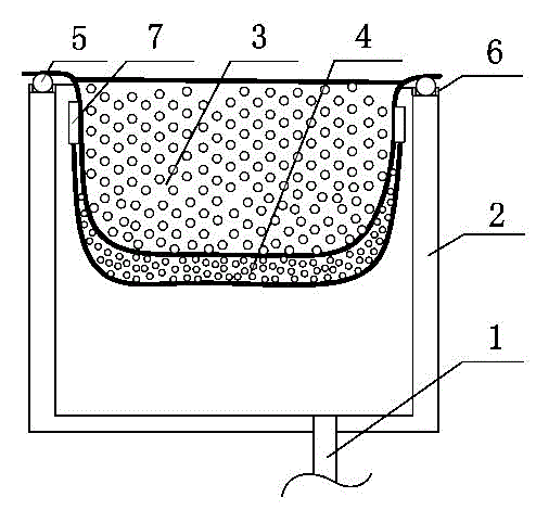
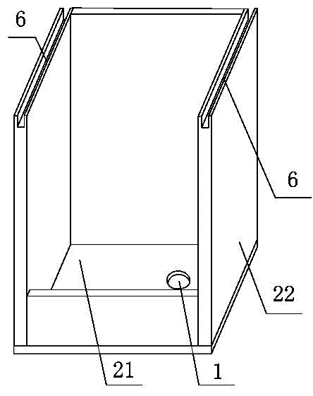
[0031] Splash-proof and labor-saving drilling fluid screening device, such as figure 1 , figure 2 and image 3 As shown, it includes a filter cylinder 2 with a discharge port 1 at the bottom, and an upper screen 3 and a lower screen 4 arranged in the filter cylinder 2, and is characterized in that:

[0032] Described filter cylinder body 2 comprises base plate 21, and the bottom end is fixed on three support plates 22 on base plate 21; One of the cuboid structures with side walls open;

[0033] The longitudinal section of the upper screen 3 is "U"-shaped, and rollers 5 are arranged on both sides of the top, and the tops of the two supporting plates 22 parallel to each other are provided with slideways 6 that cooperate with the rollers 4; The subnet 4 is fixed on the bottom end of the upper screen 3 through the connecting rod 7, and the connecting rod 7 is provided with a push-pull handle 8.

[0034] In order to facilitate the sieved drilling fluid to effectively flow out ...

Embodiment 2

[0036] The difference between this embodiment and Embodiment 1 is that a power device is also connected to the connecting rod 7 in this embodiment.

[0037] In this embodiment, the power device is a linear stepper motor.

Embodiment 3

[0039] The difference between this embodiment and Embodiment 3 is that the power device in this embodiment is preferably a linear moving cylinder.


PUM


Abstract

The invention discloses a splash-proof labor-saving drilling fluid screening device which mainly solves the problems that drilling fluid solid control filtering equipment is high in energy consumption, low in screening efficiency and inconvenient to operate in the prior art. The splash-proof labor-saving drilling fluid screening device comprises a filtering barrel body, an upper screening net and a lower screening net, wherein a discharging opening is formed in the bottom end of the filtering barrel body, and the upper screening net and the lower screening net are arranged in the filtering barrel body. The filtering barrel body comprises a bottom plate and three supporting plates with the bottom ends being fixedly arranged on the bottom plate. The discharging opening is formed in the bottom plate, and the three supporting plates constitute a cuboid structure with the top end and one of the side walls being opened. The longitudinal section of the upper screening net is in a U shape, rollers are arranged on the two sides of the top end of the upper screening net, and sliding rails which are matched with the rollers are arranged on the top end sides of the two parallel supporting plates. The lower screening net is fixed at the bottom end of the upper screening net through a connecting rod, and the connecting rod is provided with a push-and-pull handle. The splash-proof labor-saving drilling fluid screening device has the advantages of being low in energy consumption, good in filtering effect, capable of saving time and labor in cleaning operation and the like.

Description

technical field [0001] The invention relates to a screening device, in particular to a splash-proof and labor-saving drilling fluid screening device. Background technique [0002] Drilling fluid is an indispensable and important part of oil drilling operations. On the one hand, it is related to safe, fast and high-quality drilling, and on the other hand, it is related to the protection of oil and gas layers. The role of drilling fluid in the drilling process can be summarized as: protecting the hole wall, balancing the formation soil pressure, cooling and lubricating the drilling tool, providing bottom-hole power, hydraulically crushing rock, and returning bottom-hole rock samples, etc. [0003] The drilling fluid specifies a series of drilling fluid performance parameters according to actual work needs, as the basis for adjusting and controlling the drilling fluid performance. The performance parameter of drilling fluid solid phase content is one of them. The solid phase o...

Claims


Application Information

Patent Timeline
Patent Type & Authority Applications(China)
IPC IPC(8): E21B21/06B01D33/03
CPCE21B21/01
Inventor 贺昶明
Owner CHENGDU KESHENG PETROLEUM TECH
Learn More