

Leakage-proof pressure-bearing hydraulic cylinder
A hydraulic cylinder and anti-leakage technology, applied in the field of hydraulic machinery, can solve problems such as flattening and leakage of sealing rings, and achieve the effect of improving sealing performance
- Summary
- Abstract
- Description
- Claims
- Application Information
AI Technical Summary
Problems solved by technology
Method used
Image

Examples
Embodiment Construction
[0012] The present invention will be further described in detail below through the specific examples, the following examples are only descriptive, not restrictive, and cannot limit the protection scope of the present invention with this.
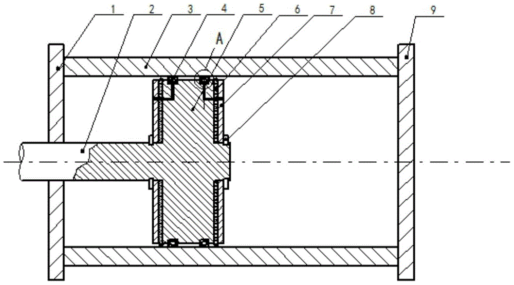
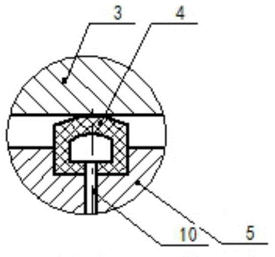
[0013] An anti-leakage pressurized hydraulic cylinder, comprising a left cylinder head 1, a right cylinder head 9, a cylinder barrel 3, a cylinder rod 2, a piston 5 and a pressure bearing plate 7, which are coaxially fixed between the left cylinder head and the right cylinder head Cylinder, coaxial sliding piston in the cylinder, the piston and the cylinder rod are coaxially produced in one body; the pressure bearing plates are symmetrically installed on the front and rear diameter surfaces of the piston, and the pressure bearing plates are coaxially fixed by the snap ring 8 On the piston, a seal 6 is installed coaxially between the pressure bearing plate and the radial surface of the piston.
[0014] The innovation point of the present inve...
PUM
 Abstract
Description
Claims
Application Information