Supercharge Your Innovation With Domain-Expert AI Agents!

Flow divider, heat exchanger and air conditioner

A shunt and heat exchanger technology, applied in evaporator/condenser, fluid circulation arrangement, lighting and heating equipment, etc., can solve the problems of uneven shunt, complicated process, complicated shunt processing, etc., to improve the mixing uniformity degree, improve the effect of the diversion effect

Inactive Publication Date: 2015-05-13
GREE ELECTRIC APPLIANCES INC
View PDF6 Cites 0 Cited by
  • Summary
  • Abstract
  • Description
  • Claims
  • Application Information

AI Technical Summary

Problems solved by technology

[0003] 1. The space position is highly required, and the direction of the shunt must be placed vertically upward or downward, otherwise the uniformity of the shunt will be reduced;
[0004] 2. Occupying space, the shunt and shunt capillary have a minimum space size requirement, and the heat exchanger needs to reserve a large assembly space;
[0005] 3. The process is complicated and unreliable. The shunt capillary and the shunt are connected by welding, the process is complicated, and it is easy to cause problems such as welding blockage and overheating;
[0006] 4. The processing of the shunt is complicated, and it is difficult to ensure the uniformity of the shunt. For the heat exchanger with a large number of shunts, the shunt is difficult to process and the uniformity of the shunt is difficult to guarantee;
[0007] 5. The mixing degree of the gas-liquid two-phase working medium is low, especially for the system where the throttling is on the condenser side and the flow is split on the evaporator side. The degree of mixing of liquid and two phases is low;
[0008] 6. Abnormal noise. The working medium enters the shunt from the copper pipe, and then shunts. After many times of drastic changes in the cross-sectional area of ​​the flow path, there is often abnormal noise.
[0009] To sum up, if the flow in the heat exchanger is uneven, the flow rate of the working fluid in the copper tubes of each branch will be different.
Under the same heat exchange conditions, due to the different flow rate of the working medium in each branch copper tube, the heat exchanger efficiency of each branch copper tube will be different, which will reduce the overall heat exchange efficiency and utilization of the heat exchanger as a whole. Rate

Method used


Image

  • Flow divider, heat exchanger and air conditioner
  • Flow divider, heat exchanger and air conditioner
  • Flow divider, heat exchanger and air conditioner

Examples


Embodiment Construction

[0027] The present invention will be described in detail below with reference to the accompanying drawings and examples.

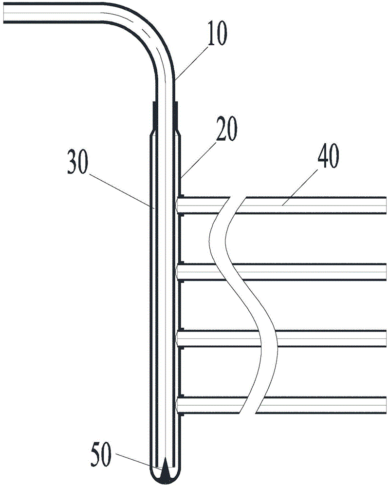
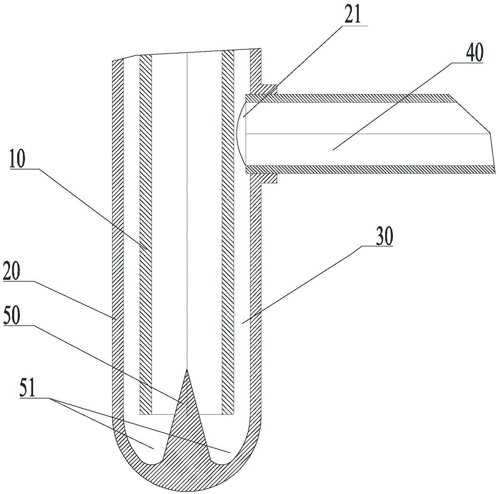
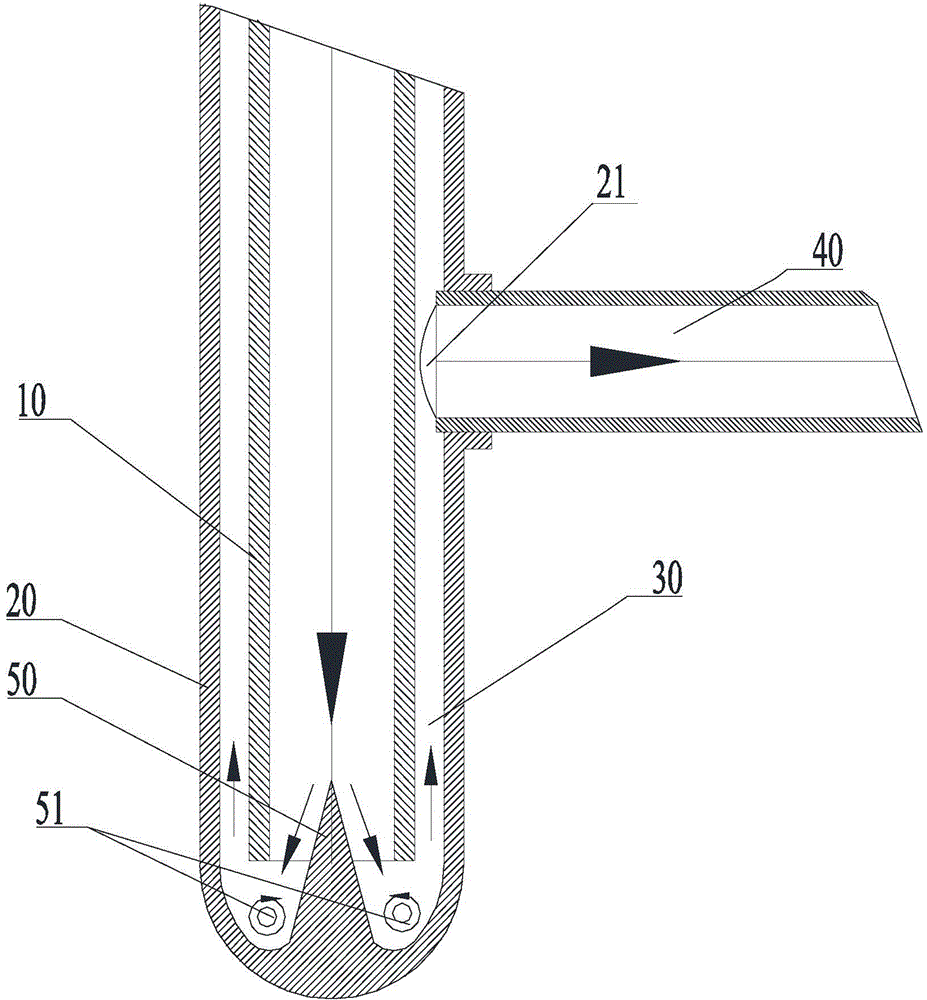
[0028] Such as Figure 1 to Figure 3 As shown, the flow divider according to the present invention includes an inner tube 10 and an outer tube 20, the outer tube 20 is sleeved outside the inner tube 10 and forms a split cavity 30 between the inner tube 10 and the outer tube 20, and the outer tube 20 is provided There are a plurality of branch pipe interfaces 21 communicating with the distribution chamber 30; the first end of the outer tube 20 is in sealing connection with the outer wall of the inner tube 10, the second end of the outer tube 20 is a closed end, and the second end of the inner tube 10 is an open end , and communicate with the split chamber 30; the inner wall of the second end of the outer tube 20 is provided with a split cone 50 facing the second end of the inner tube 10. In the present invention, by setting the splitter cone 50 towards the...


PUM


Abstract

The invention provides a flow divider, a heat exchanger and an air conditioner. The flow divider comprises an inner pipe and an outer pipe, the outer pipe is arranged outside the inner pipe in a sleeving mode, and a flow dividing cavity is formed between the inner pipe and the outer pipe. A plurality of branch pipe connectors communicated with the flow dividing cavity are formed in the outer pipe, a first end of the outer pipe is connected with the outer wall of the inner pipe in a sealed mode, a second end of the outer pipe is a closed end, a second end of the inner pipe is an open end and communicated with the flow dividing cavity, and a flow dividing cone facing the second end of the inner pipe is arranged on the inner wall of the second end of the outer pipe. As the flow dividing cone facing the second end of the inner pipe is arranged on the inner wall of the second end of the outer pipe, when reaching the flow dividing end (the second end), a gas working medium and a liquid working medium in the inner pipe firstly make contact with the flow dividing cone. In the flowing process of the working media, as the section area between the flow dividing cone and the inner wall of the inner pipe gradually becomes smaller, the flow rate is increased, the mixing uniformity of the gas working medium and the liquid working medium is improved, the mixed working media are evenly distributed to all flow dividing branch pipes, and the flow dividing effect is improved.

Description

technical field [0001] The invention relates to the field of heat exchange devices, in particular to a flow divider, a heat exchanger, and an air conditioner. Background technique [0002] In the prior art, the general working fluid splitting method of the copper tube heat exchanger is "copper tube + flow divider + liquid separation capillary". This diversion method has limitations, and it is difficult to divide the gas-liquid two-phase working fluid evenly, as follows: [0003] 1. The space position is highly required, and the direction of the shunt must be placed vertically upward or downward, otherwise the uniformity of the shunt will be reduced; [0004] 2. Occupying space, the shunt and shunt capillary have a minimum space size requirement, and the heat exchanger needs to reserve a large assembly space; [0005] 3. The process is complicated and unreliable. The shunt capillary and the shunt are connected by welding, the process is complicated, and it is easy to cause ...

Claims


Application Information

Patent Timeline
Patent Type & Authority Applications(China)
IPC IPC(8): F25B41/00F25B41/40
CPCF25B39/00F25B39/028F25B41/00F25B2500/09F25B2500/12
Inventor 陈华康李胤媛梁桂源胡朝发丁飞罗志明位向前杨海邹大枢陈思磊胥宗朋罗星罗智越
Owner GREE ELECTRIC APPLIANCES INC
Features
  • R&D
  • Intellectual Property
  • Life Sciences
  • Materials
  • Tech Scout
  • Unparalleled Data Quality
  • Higher Quality Content
  • 60% Fewer Hallucinations
Learn More