
Placement device and operation method for tsp blast hole emulsion explosive

An emulsion explosive and blast hole technology, applied in blasting and other directions, can solve the problems of accurate judgment affecting the stability of the surrounding rock on the front face, the crushed stone damage of the hole wall of the electronic detonator detonator, and the difficulty of the explosive card reaching the standard depth, etc. Achieve the effect of improving placement efficiency, humanized design and simple structure

Active Publication Date: 2017-01-04
SHANDONG UNIV
View PDF7 Cites 0 Cited by
  • Summary
  • Abstract
  • Description
  • Claims
  • Application Information

AI Technical Summary

Problems solved by technology

However, in the process of TSP prediction, it is necessary to place the emulsion explosive containing the electric detonator detonator in the blast hole, but due to the blockage of the hole by silt and gravel, it often happens that the explosive is stuck in the middle of the blast hole and it is difficult to reach the specified depth or the electronic detonator is touched. The gravel damage of the hole wall cannot be detonated normally. These factors affect the propagation of seismic waves in the surrounding rock of the tunnel, thus affecting the accurate judgment of the stability of the surrounding rock at the face of the tunnel ahead. Wrong advanced geological prediction will delay the construction period, and in serious cases will cause Occurrence of Engineering Accidents

Method used


Image

  • Placement device and operation method for tsp blast hole emulsion explosive
  • Placement device and operation method for tsp blast hole emulsion explosive
  • Placement device and operation method for tsp blast hole emulsion explosive

Examples


Embodiment Construction

[0029] The present invention will be further described in detail below in conjunction with the accompanying drawings and specific embodiments.

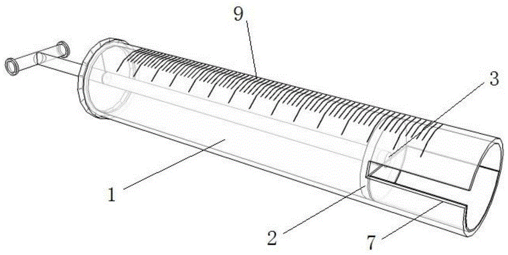
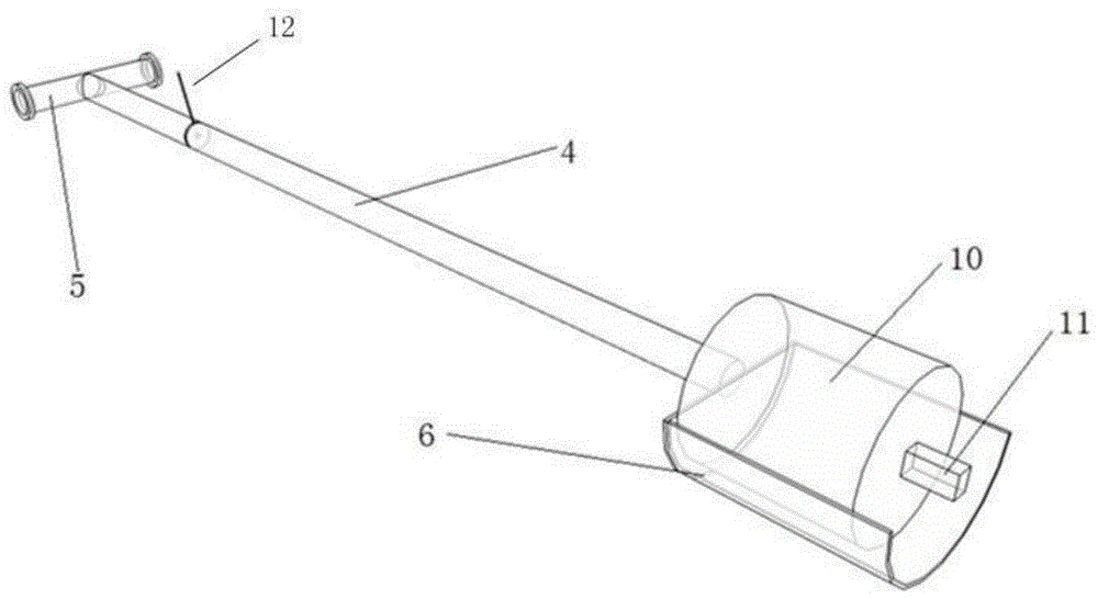
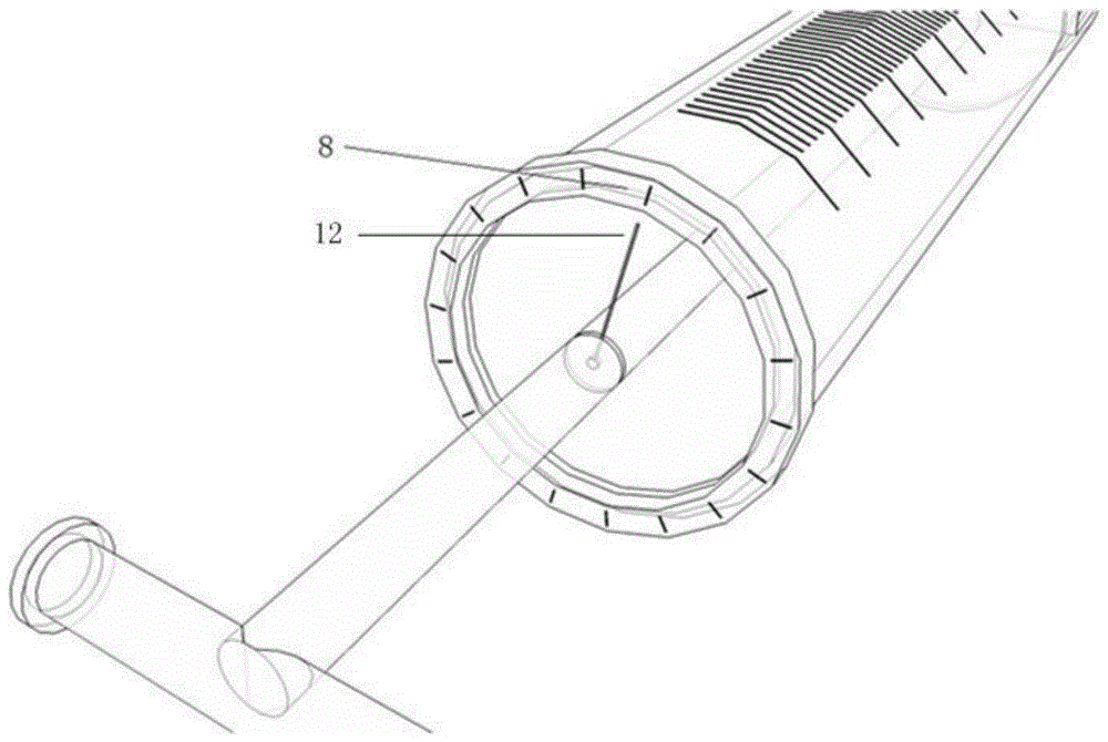
[0030] The placement device for TSP blasthole emulsion explosives includes a stainless steel protective sleeve 1, inside which is fixed a separator 2 in the cylinder, with a sleeve opening groove 7 at the front end, and a separator hole 3 in the cylinder inner separator 2 for the purpose of The core connecting rod 4 passes through, and the two ends of the barrel core connecting rod 4 are respectively connected to the explosive placement bucket 6 and the rotating hand lever 5, and the three are consolidated into one; the depth of entering the blast hole is adjusted by pumping the barrel core connecting rod 4, and the depth can be determined by Measured by the scale 9; the pointer 12 and the angle scale 8 form an angle measuring device together, which can measure the rotation angle of the rotating hand lever 5.

[0031] The stainless st...


PUM


Abstract

The invention relates to a placing device for a TSP blast hole emulsion explosive and an operation method. The placing device comprises a stainless steel protective sleeve, an in-sleeve separation sheet is fixed to the interior of the stainless steel protective sleeve, a sleeve open slot is formed in the front end of the stainless steel protective sleeve, a separation sheet hole is formed in the in-sleeve separation sheet so that a sleeve core connecting rod can penetrate, the two ends of the sleeve core connecting rod are connected with an explosive placing hopper and a rotary handle, and the sleeve core connecting rod, the explosive placing hopper and the rotary handle are fixedly connected into a whole. The depth of the portion, entering a blast hole, of the sleeve core connecting rod can be adjusted through extraction according to measurement of a dividing rule and the rotation angle of the rotary handle can be acquired through an angle measurement device. By the adoption of the novel placing device for the TSP blast hole emulsion explosive and the operation method, the emulsion explosive and an electronic detonator exploder can not be affected by slurry and gravel hole blockage under the protection of the rigid sleeve, and the success rate of TSP blast hole detonation is increased; meanwhile, the device is simple in structure and convenient to operate, the explosive can be transported to the position of the preset depth of the blast hole only by extracting and rotating the sleeve core connecting rod and placing efficiency of the TSP blast hole emulsion explosive can be greatly improved.

Description

technical field [0001] The invention relates to a placement device and an operation method for emulsified explosives of TSP blastholes. Background technique [0002] TSP (Tunnel Seismic Prediction ahead) method, that is, earthquake prediction in front of the tunnel or advanced geological prediction, refers to the arrangement of excitation holes within a certain range of the side wall near the tunnel face, and artificially stimulates seismic waves in the holes, and the generated seismic waves are in the form of spherical waves. When the wave impedance of the surrounding rock changes (such as encountering karst, fault or rock formation interface), part of the seismic wave will be reflected back, and the other part of the seismic wave will continue to propagate forward. The reflected seismic waves are received by high-precision receivers and transmitted to the host computer to form seismic wave records. However, in the process of TSP prediction, it is necessary to place the em...

Claims


Application Information

Patent Timeline
Patent Type & Authority Patents(China)
IPC IPC(8): F42D1/14
Inventor 李利平孙尚渠李术才张乾青徐飞许振浩石少帅张骞王康王本硕
Owner SHANDONG UNIV
Learn More