An adjustable rectangular aperture

A rectangular aperture and U-shaped technology, applied in the field of optical structure, can solve the problems of small-sized apertures that are difficult to process and difficult rectangular apertures, and achieve good processing performance, easy use, and good stability.

Inactive Publication Date: 2017-01-04
NAT ASTRONOMICAL OBSERVATORIES CHINESE ACAD OF SCI
View PDF6 Cites 0 Cited by
  • Summary
  • Abstract
  • Description
  • Claims
  • Application Information

AI Technical Summary

Problems solved by technology

[0008] In order to solve the problem that the traditional diaphragm technology is difficult to realize the continuous adjustable rectangular diaphragm that the rectangle does not rotate during adjustment, and at the same time solve the problem that the small-sized diaphragm is difficult to process, the purpose of the present invention is to make the diaphragm shape regular, the edges coplanar, and each Adjustable rectangular aperture with neat and sharp edges

Method used


Image

  • An adjustable rectangular aperture
  • An adjustable rectangular aperture
  • An adjustable rectangular aperture

Examples


Embodiment Construction

[0030] In order to make the objectives, technical solutions, and advantages of the present invention clearer, the following further describes the present invention in detail in conjunction with specific embodiments and with reference to the accompanying drawings.

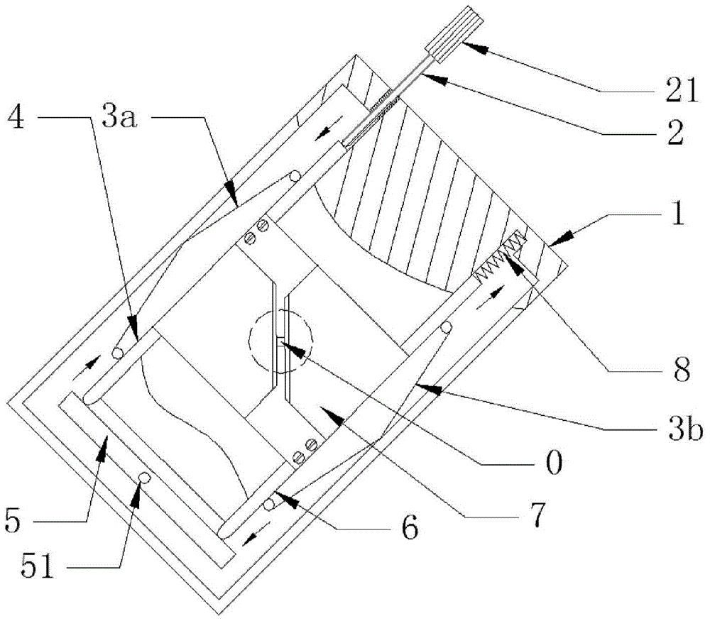
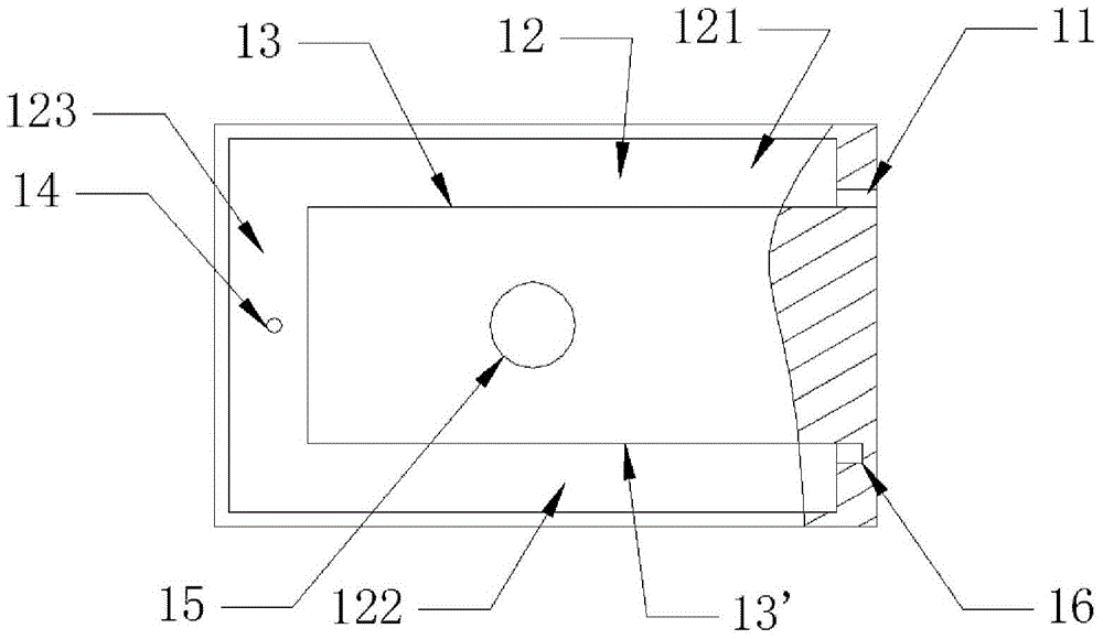
[0031] See figure 1 Shows the overall structure of the adjustable rectangular aperture of the present invention. The adjustable rectangular aperture includes a frame 1, a spiral mechanism 2, a first spring 3a, a second spring 3b, a first slider 4, a lever 5, and a second slider. Block 6, two blades 7 and third spring 8; see figure 2 The rack 1 shown includes: a mounting hole 11, a U-shaped long groove 12, a guide rail surface 13, a shaft hole 14, a light-passing hole 15, and a receiving part 16, wherein:

[0032] The frame 1 has a rectangular structure. The center of the frame 1 is provided with a light-passing hole 15 for light transmission; a U-shaped long slot 12 is provided in the frame 1;

[0033] A mounting hole 11 ...


PUM


Abstract

The present invention is an adjustable rectangular diaphragm comprising: a frame, a screw mechanism, a first spring, a second spring, a first slider, a second slider, a lever, and two blades; The installation hole and the accommodating part of the fixed spring communicate with the position corresponding to the U-shaped long slot; the U-shaped long slot with three slots is located at the edge of the frame; the first spring and the first slider are placed at the bottom of the first slot; Place the second spring and the second slider at the bottom of the second groove; insert the lever of the protruding shaft in the third groove; the top of the screw mechanism is in contact with the plane of the first slider; one end of the third spring is placed in the accommodating part Among them, the other end of the third spring is in contact with one end of the second slider; the two blades are symmetrically placed on the upper surface of the frame; each blade is fixedly connected with the corresponding first and second sliders, and the right-angled blade of each blade The surface is located at the corresponding position on the upper surface of the frame, and the right-angled blades corresponding to the two blades are placed opposite to each other to form a matching rectangular opening, forming an adjustable rectangular aperture.

Description

Technical field [0001] The invention belongs to the technical field of optical structures, and specifically relates to an adjustable rectangular aperture. Background technique [0002] Aperture is used to limit the size of the imaging beam or the range of the imaging space on the edge, frame or specially set apertured barrier of the optical element in the optical tool assembly. It is usually round or rectangular. Optical experiments often require an adjustable aperture. [0003] Usually the adjustable diaphragm is composed of multiple pieces, approximately forming a circle. Even if it is made into 4 elements, when the size of the diaphragm is changed, the four sides rotate and cannot be used as a field diaphragm. In addition, due to the thickness of the blades, the diaphragm cannot be closed very small. [0004] Normal slits can be closed very small, but they can only restrict one direction. If another slit is used to restrict the other direction, since the four sides are not on th...

Claims


Application Information

Patent Timeline
Patent Type & Authority Patents(China)
IPC IPC(8): G02B7/00
CPCG02B7/00G02B5/00
Inventor 郭永卫
Owner NAT ASTRONOMICAL OBSERVATORIES CHINESE ACAD OF SCI
Why Eureka
Try Eureka