Mask plate, method for manufacturing color film substrate, and color film substrate

A technology for a color filter substrate and a mask plate is applied in the fields of methods and color filter substrates, masks and manufacturing of color filter substrates, which can solve the problems of lowering contrast, increasing production costs, reducing transmittance of color filter substrates, etc. The effect of high pass rate, improving production efficiency and good transmittance

Inactive Publication Date: 2015-05-13
HEFEI BOE OPTOELECTRONICS TECH +1
View PDF5 Cites 12 Cited by
  • Summary
  • Abstract
  • Description
  • Claims
  • Application Information

AI Technical Summary

Problems solved by technology

In order to prevent light leakage, the color filter layer 03 and the black matrix layer 02 must overlap to a certain extent. In order to avoid the impact of the step difference in the overlapping part on the picture quality, it is necessary to add a flat layer 04, which will add a process and increase production. cost, and the flat layer 04 will reduce the transmittance of the color filter substrate, resulting in a decrease in contrast

Method used


Image

  • Mask plate, method for manufacturing color film substrate, and color film substrate
  • Mask plate, method for manufacturing color film substrate, and color film substrate
  • Mask plate, method for manufacturing color film substrate, and color film substrate

Examples


Embodiment Construction

[0039] The following will clearly and completely describe the technical solutions in the embodiments of the present invention with reference to the accompanying drawings in the embodiments of the present invention. Obviously, the described embodiments are only some, not all, embodiments of the present invention. Based on the embodiments of the present invention, all other embodiments obtained by persons of ordinary skill in the art without making creative efforts belong to the scope of patent protection of the present invention.

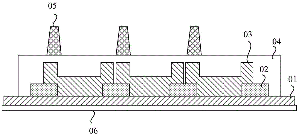
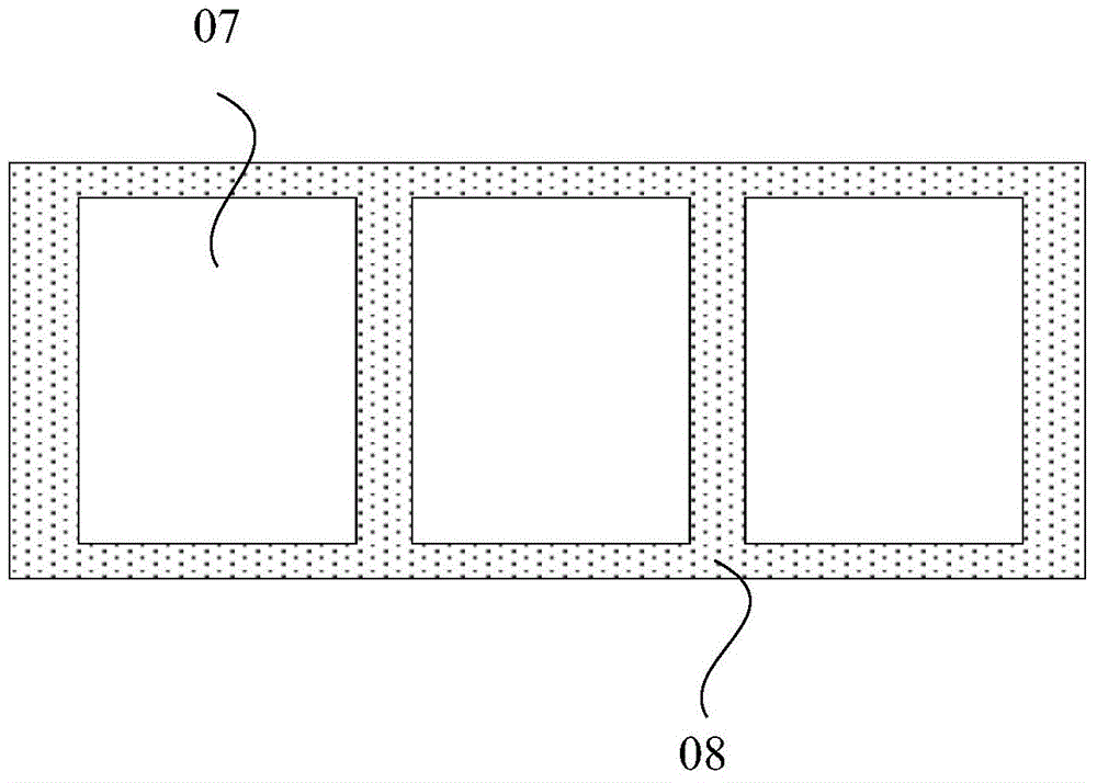
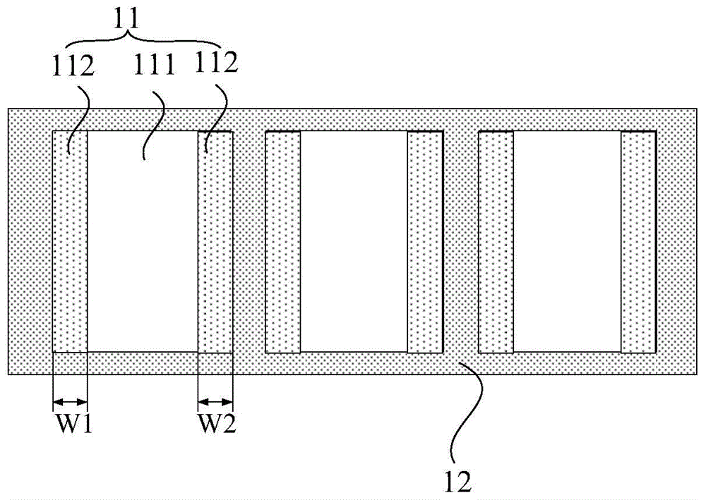
[0040] like image 3 and Figure 4 shown, where: image 3 Schematic diagram of the structure of the mask plate provided by the embodiment of the present invention; Figure 4 Schematic diagram of the structure of the color filter plate provided by the embodiment of the present invention; the present invention provides a mask plate, including: a first region 11 corresponding to each sub-pixel unit, and a second region between two adjacent first regio...


PUM

PropertyMeasurementUnit
thicknessaaaaaaaaaa
thicknessaaaaaaaaaa

Abstract

The invention discloses a mask plate, a method for manufacturing a color film substrate, and the color film substrate. The mask plate is used for reducing range difference of a color filter layer and improving transmittance of the color film substrate so as to improve a display effect of a display substrate. The mask plate comprises first regions and second regions, wherein each first region corresponds to each sub pixel unit; each second region is positioned between every two adjacent first regions; each first region is respectively provided with a first sub region for forming a color filter layer pattern positioned in an open region of a black matrix layer and two second sub regions for forming color filter layer patterns positioned in non-open regions of the black matrix layer; each first sub region is positioned between every two corresponding second sub regions; transmittance of each second sub region is gradually decreased or increased along the set length in the direction far away from the corresponding first sub region.

Description

technical field [0001] The invention relates to the field of display technology, in particular to a mask plate, a method for manufacturing a color filter substrate, and the color filter substrate. Background technique [0002] In the existing TFT-LCD CF (Color Filter color filter) process, such as figure 1 and figure 2 shown, where: figure 1 is a schematic structural diagram of a color filter substrate in the prior art, figure 2 It is a schematic structural diagram of a mask plate in the prior art. The mask plate in the prior art generally includes: a first region 07 corresponding to each sub-pixel unit one-to-one, and a first region 07 located between two adjacent first regions 07 In the second area 08, the photoresist used in the color filter layer is generally a negative photoresist, so the first area 07 of the mask is fully transparent, and the second area 08 is fully impermeable, forming a color filter layer pattern as figure 1 As shown, the color filter substrat...

Claims


Application Information

Patent Timeline
Patent Type & Authority Applications(China)
IPC IPC(8): G03F1/54G02F1/1335G02F1/1339
CPCG02B5/201G02F1/133512G02F1/133516G03F7/0007G03F1/54G02F1/133514G02F1/1339
Inventor 成学佩尹冬冬余学权李志强
Owner HEFEI BOE OPTOELECTRONICS TECH
Why Eureka
Try Eureka