
Radio frequency configuration method, device and terminal

A configuration method and technology for configuring devices, which are applied in the directions of program control devices, electrical components, transmission systems, etc., can solve problems such as the inability of RF drivers to adapt to multiple RF hardware circuits.

Inactive Publication Date: 2015-05-13
YULONG COMPUTER TELECOMM SCI (SHENZHEN) CO LTD
View PDF5 Cites 12 Cited by
  • Summary
  • Abstract
  • Description
  • Claims
  • Application Information

AI Technical Summary

Problems solved by technology

[0004] The technical problem to be solved by the present invention is to provide a radio frequency configuration method, device and terminal to solve the problem that the prior art radio frequency driver cannot adapt to multiple radio frequency hardware circuits

Method used


Image

  • Radio frequency configuration method, device and terminal
  • Radio frequency configuration method, device and terminal
  • Radio frequency configuration method, device and terminal

Examples


Embodiment Construction

[0031] The present invention will be described in further detail below in conjunction with the accompanying drawings and embodiments. It should be understood that the specific embodiments described here are only used to explain the present invention, not to limit the present invention.

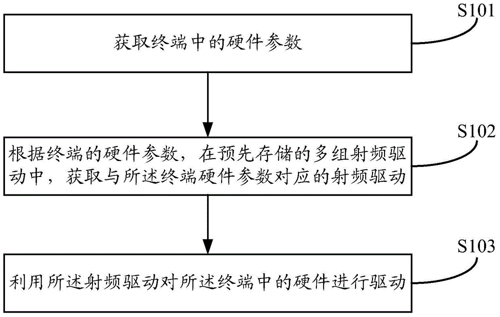
[0032] figure 2 As shown, the embodiment of the present invention relates to a radio frequency configuration method, including:

[0033] Step S101, acquiring hardware parameters in the terminal;

[0034] Step S102, according to the hardware parameters of the terminal, obtain the radio frequency driver corresponding to the terminal hardware parameters among the multiple groups of radio frequency drivers stored in advance;

[0035] Step S103, using the acquired radio frequency driver to drive the hardware in the terminal.

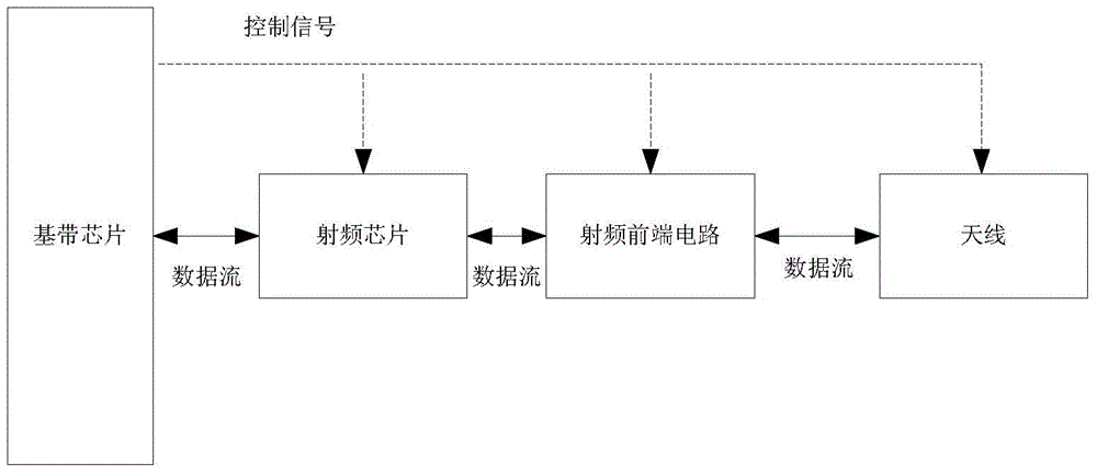
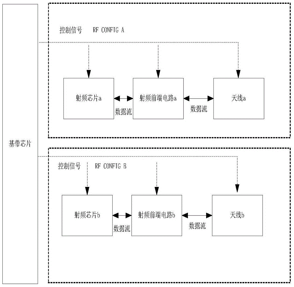
[0036] The hardware parameters of the terminal include: radio frequency chip parameters, radio frequency front-end circuit parameters and antenna parameters. As for the ...


PUM


Abstract

The invention discloses a radio frequency configuration method, device and terminal. The method comprises obtaining hardware parameters in the terminal; according to the hardware parameters of the terminal, obtaining a radio frequency driver corresponding to the hardware parameters of the terminal; driving hardware in the terminal through the radio frequency driver. According to the radio frequency configuration method, by setting a plurality of groups of radio frequency drivers, when having change in radio frequency circuits or needing to adapt to different radio frequency circuits, the hardware in the terminal can be driven by searching for the corresponding radio frequency driver in the plurality of groups of radio frequency drivers without operations of redesigning driving software, burning software or the like, so that the speed of debugging, researching and developing products can be increased.

Description

technical field [0001] The present invention relates to the technical field of mobile terminals, in particular to a radio frequency configuration method, device and terminal. Background technique [0002] The current multi-mode intelligent terminal RF and front-end system structure is as follows: figure 1 shown. Multi-mode chips support more and more modes, and the front-end circuit design and antenna design will become more and more complex. The baseband software must effectively and accurately control these devices to ensure the normal communication of the terminal. The current solution is mainly based on the design of the RF chip, RF front-end circuit and antenna, adapting the fixed driver code, loading the RF driver after the system is running, and calling the driver to configure these RF devices to work in a specific mode in a specific scenario. [0003] The existing solution is only designed for specific hardware and loads the corresponding driver software. There a...

Claims


Application Information

Patent Timeline
IPC IPC(8): H04B1/40G06F9/44
CPCH04B1/40
Inventor 肖念
Owner YULONG COMPUTER TELECOMM SCI (SHENZHEN) CO LTD
Learn More