Eureka AIR delivers breakthrough ideas for toughest innovation challenges, trusted by R&D personnel around the world.

Compact and stable high-peak-power optical fiber output laser

A high-peak, laser technology, applied in the direction of lasers, laser components, phonon exciters, etc., can solve the problems of reduced spatial optical coupling efficiency, low output energy, poor laser stability, etc., to reduce the risk of fiber damage, The effect of increasing peak power and improving stability

Inactive Publication Date: 2016-03-09
NANJING INST OF ADVANCED LASER TECH
View PDF5 Cites 11 Cited by
  • Summary
  • Abstract
  • Description
  • Claims
  • Application Information

AI Technical Summary

Problems solved by technology

[0003] However, the disadvantages of the existing passive Q-switching technology are: but because there is no external control, the accuracy of the performance is not high, the stability of the output beam is poor, and the output energy is lower than that of active Q-switched lasers
[0004] It is more difficult to debug the coupling of spatial light into multimode fiber. What is more critical is the design of the fiber fixture, such as end face protection, heat dissipation, stability, etc., as well as the stability of the spatial light itself, often due to the stability of the high peak power laser itself. Poor, especially the deformation generated on the mechanical structure, which leads to the reduction of the spatial optical coupling efficiency and damages the end face of the fiber, so that the stability of the laser product cannot be guaranteed

Method used


Image

  • Compact and stable high-peak-power optical fiber output laser
  • Compact and stable high-peak-power optical fiber output laser

Examples


Embodiment Construction

[0019] The present invention will be further described through the embodiments below in conjunction with the accompanying drawings, so as to better understand the present invention.

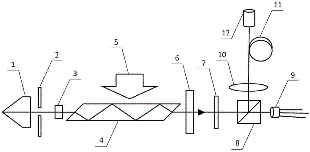
[0020] like figure 1 As shown, a compact and stable high peak power fiber output laser, including a resonant cavity, a half-wave plate (7), a polarization beam splitter (8) and a photodetector (9), are arranged in sequence along the optical path direction, and it is characterized in that, The resonant cavity includes a Paul prism (1), a passive Q-switching crystal (3), a laser crystal (4) and an output mirror (6) arranged in sequence; A coupling lens (10), an optical fiber (11) and a collimator lens group (12) are provided in sequence.

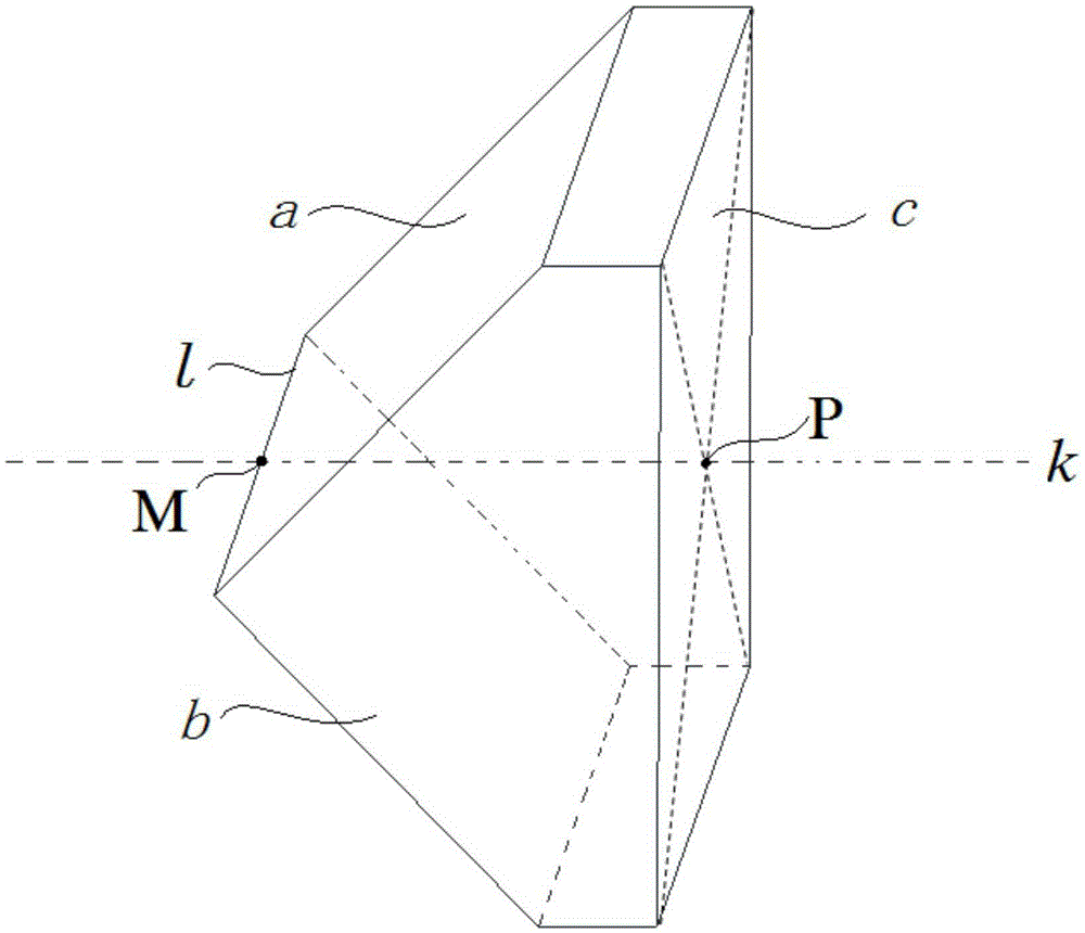
[0021] like figure 2 As shown, the Paul prism 1 includes two inclined planes a and b perpendicular to each other, a and b intersect on the line l, the midpoint of l is M, the Paul prism 1 also includes a longitudinal plane c, and the longitudinal plane c is a ...


PUM


Abstract

The invention discloses a compact and stable high-peak-power optical fiber output laser. The laser comprises a resonant cavity, pumping sources, a half-wave plate, a polarization beam splitter, a photoelectric detector, a coupling lens, an optical fiber and a collimating lens group, wherein the resonant cavity comprises a Porro prism, a passive Q-modulation crystal, a laser crystal and an output mirror; in the compact and stable high-peak-power optical fiber output laser, the Porro prism, the passive Q-modulation crystal, the laser crystal, the output mirror, the half-wave plate, the polarization beam splitter and the photoelectric detector are arranged in sequence in a light path direction of laser; the pumping sources are uniformly arranged in the center of the laser crystal by using stack arrays; the polarization beam splitter splits the laser into a branch light path perpendicular to the light path; the laser on the branch light path enters the optical fiber through the coupling lens; and the collimating lens group is arranged at the end of the branch light path. According to the compact and stable high-peak-power optical fiber output laser, the stability of a system is ensured, the risk of optical fiber damage is lowered, and the peak power of the optical fiber output laser is indirectly increased.

Description

technical field [0001] The invention relates to the technical field of fiber lasers, in particular to a compact and stable high peak power fiber output laser. Background technique [0002] Nowadays, pulsed lasers are widely used in many fields, but the peak power output by existing pulsed lasers is far from meeting the requirements of many important practical applications. For this problem, a solution is to use Q-switching technology. Q-switching technology, also known as Q-switching technology, is a technology that compresses the generally output continuous laser energy into extremely narrow pulses for emission, so that the peak power of the light source can be increased by several orders of magnitude. Today, Q-switching technology is an important means of obtaining megawatt-level peak power lasers. The methods for implementing Q-switching are mainly divided into active Q-switching and passive Q-switching. Passive Q-switching does not require high-voltage, fast electro-o...

Claims


Application Information

Patent Timeline
Patent Type & Authority Applications(China)
IPC IPC(8): H01S3/10H01S3/11H01S3/08H01S3/067
CPCH01S3/10H01S3/067H01S3/08H01S3/1112
Inventor 周军杨彬姚红权
Owner NANJING INST OF ADVANCED LASER TECH
Why Eureka
Eureka Blog
Learn More