1.064um laser range finder transmitting antenna debugging method and apparatus

A technology of laser rangefinder and transmitting antenna, which is applied in distance measurement, measuring device, line-of-sight measurement, etc. It can solve problems such as difficult interpretation and poor imaging quality, and achieve the functions of improving debugging accuracy, narrowing beam spread angle, and guaranteeing effect of distance

Inactive Publication Date: 2007-12-12
中国航空工业第一集团公司第六一三研究所
View PDF0 Cites 11 Cited by
  • Summary
  • Abstract
  • Description
  • Claims
  • Application Information

AI Technical Summary

Problems solved by technology

Since the laser transmitting antenna only performs aberration correction for the laser wavelength when designing the optical system, the imaging quality is poor at the wavelength of visible light (such as d-light or D-light) or the laser wavelength of He-Ne laser (0.6328μm)
Therefore, when

Method used


Image

  • 1.064um laser range finder transmitting antenna debugging method and apparatus
  • 1.064um laser range finder transmitting antenna debugging method and apparatus
  • 1.064um laser range finder transmitting antenna debugging method and apparatus

Examples


Embodiment

[0048] Test piece design parameters:

[0049] Working wavelength: 1.064μm;

[0050] Magnification: 8×;

[0051] Incident aperture: Φ5.5;

[0052] Exit aperture: Φ44;

[0053] Optical quality: Parallelism ≤0.05mrad.

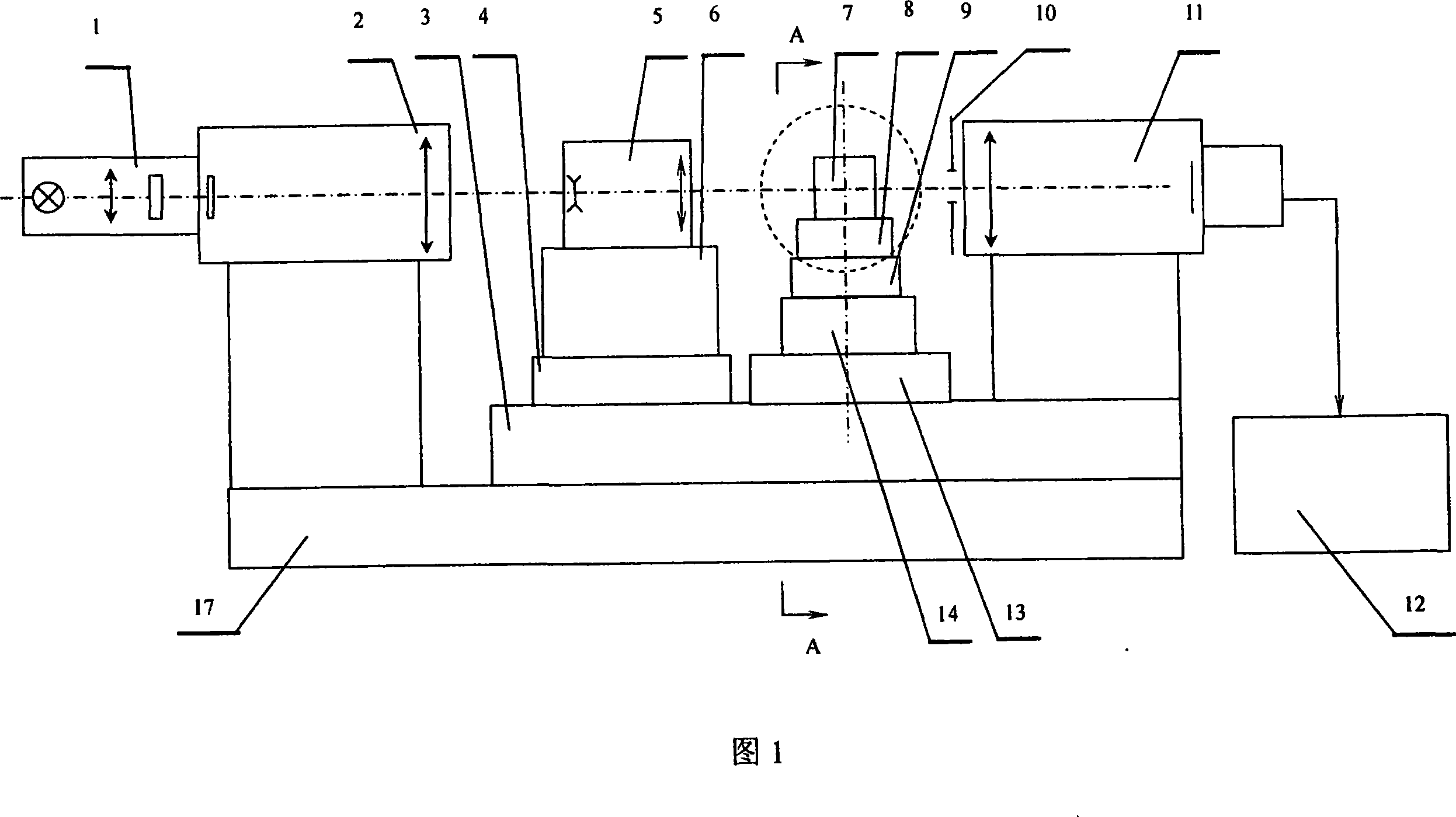
[0054] 1.064μm laser rangefinder 8× transmitting antenna debugging method:

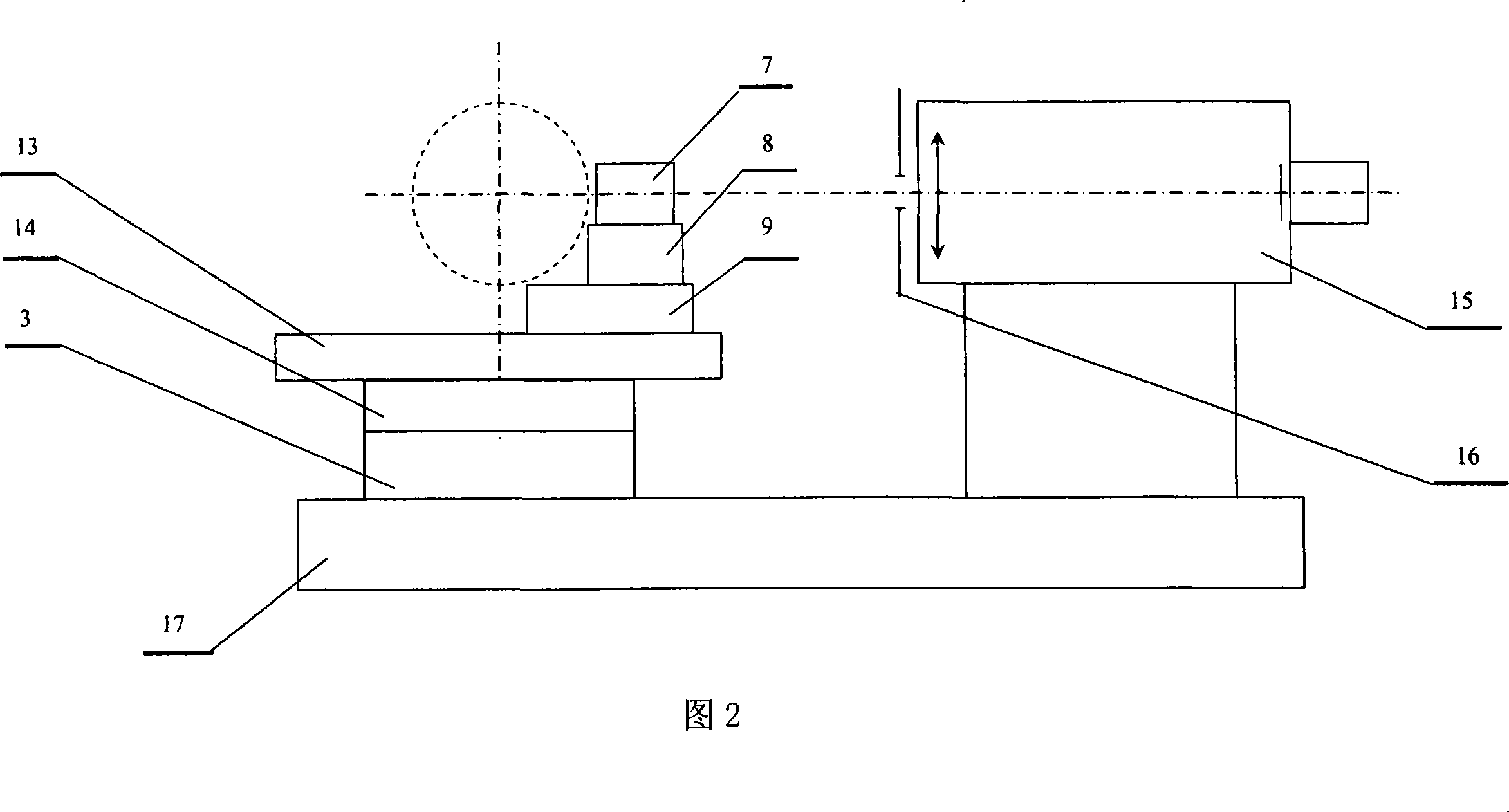
[0055] a) Install and fix the 8× laser transmitting antenna [5] on the equipment product mounting bracket [6];

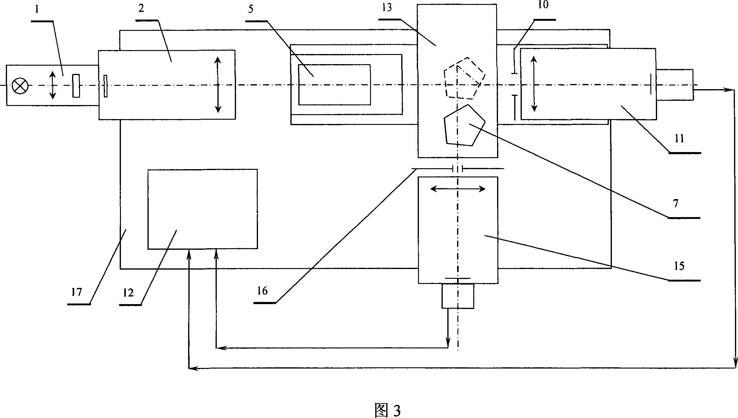
[0056] b) Turn on the power supply of the image processing system [12], and run the measurement software of the laser transmitting antenna debugging platform;

[0057] c) Turn on the power of the monochromatic light source [1], according to the caliber of the laser transmitting antenna [5], add a corresponding diaphragm [10] at the entrance pupil of the CCD front mirror [11], and the collimator [2] exits Parallel light is imaged on the CCD camera through the laser transmitting antenna [5] and the CCD front mirror [11];

[0058] d) Adjust the distance between the objectiv...


PUM


Abstract

The invention relates to an antenna modulating method and equipment for a 1.064 mu m laser distance measurement machine. It aims at the working wave length of the laser distance measurement machine, with parallel light ocular incident coming from the emitting antenna, modulating the focal surface and repetition of the focal surface of the ocular, when the object lens overlaps with the focal surface of the object lens and ocular lens, with beam from the object lens as parallel light.

Description

[0001] Technical field: The present invention relates to a method and debugging equipment for debugging the transmitting antenna of a 1.064 μm laser range finder. Background technique [0002] The radiator of the 1.064μm laser range finder emits a laser radiation beam, which is emitted after the beam is expanded by the transmitting antenna. The laser beam irradiates the target and produces diffuse reflection. The reflected light is focused on the photodetector by the receiving antenna. After being processed by the receiving circuit, Calculate the distance from the target to the machine. [0003] The beam divergence angle of the laser beam pulse output by the laser radiator is relatively large, and the beam must be expanded through the laser transmitting antenna to narrow the beam divergence angle of the laser beam pulse in order to increase the operating distance. [0004] The optical system of the laser transmitting antenna belongs to the telescopic system, which is composed ...

Claims


Application Information

Patent Timeline
IPC IPC(8): G01S7/497G01S17/08G01C3/00
Inventor 张宏斌
Owner 中国航空工业第一集团公司第六一三研究所
Why Eureka
Try Eureka