All-fiber precision variable optical attenuator

A dimming attenuation and all-fiber technology, applied in the field of optical fiber communication, can solve the problems that hinder the improvement of the dynamic range and precision of the fiber attenuator, limit the dynamic range and precision of the fiber attenuator, and the size cannot be too large, etc., to achieve the use mode Flexibility, lower implementation costs, and increased dynamic range

Inactive Publication Date: 2011-10-05
XIAN JINHE OPTICAL TECH
View PDF4 Cites 4 Cited by
  • Summary
  • Abstract
  • Description
  • Claims
  • Application Information

AI Technical Summary

Problems solved by technology

[0007] Chinese patents 01217692.3, 01271511.5 and 03277454.0 provide all-fiber attenuator solutions based on the macrobending loss of the optical fiber to realize the adjustable optical attenuator, and only use a small part of the optical fiber to realize the bending loss. According to the above formula, which limits the dynamic range and accuracy of the fiber attenuator
[0008] The solution provided by Chinese patent 200520025797.7 is to realize the adjustable optical attenuator mainly based on the microbending loss of the optical fiber, which makes full use of the length of the optical fiber used to realize the bending loss, but because it is realized by two upper and lower plates, the flat plate The size of the fiber attenuator cannot be too large, so that the length of the fiber that can be bent is limited, which hinders the improvement of the dynamic range and accuracy of this type of fiber attenuator
In addition, the adjustable distance of the relative movement of the two plates is only a few hundred microns at most, and the two plates must be kept basically parallel during the movement, so this type of attenuator has high requirements for the mechanical structure of the adjustment, which not only increases the implementation cost, It also limits the improvement of the dynamic range and precision of this type of fiber attenuator

Method used


Image

  • All-fiber precision variable optical attenuator
  • All-fiber precision variable optical attenuator
  • All-fiber precision variable optical attenuator

Examples


Embodiment 1

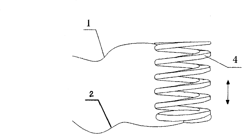
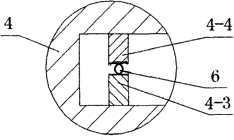
[0049] Such as figure 1 , figure 2 As shown, the present invention includes a curved casing 4 and a plurality of A-side deformation teeth 4-4 and a plurality of B-side deformation teeth continuously arranged on opposite sides of the interior of the curved casing 4 along the longitudinal direction of the curved casing 4. 4-3, when the relative positions of the two ends of the curved housing 4 change, the position between the A-side deformation teeth 4-4 and the B-side deformation teeth 4-3 inside the curved housing 4 also changes, and the A-side deformation The teeth 4-4 and the B-side deformed teeth 4-3 are arranged in a staggered manner, and a light-guiding optical fiber 6 is clamped between the two deformed teeth, and the A-side deformed teeth 4-4 and the B-side deformed teeth 4-3 are correspondingly arranged on the guide On both sides of the optical fiber 6, the two ends of the light guiding fiber 6 are respectively connected to the optical fiber 1 for inputting optical s...

Embodiment 2

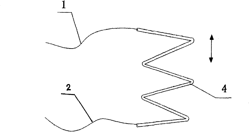
[0052] Such as image 3 , Figure 4 As shown, in this embodiment, the difference from Embodiment 1 is that the curved housing 4 is in a Z-shape as a whole, and the cross-sectional shape of the curved housing 4 is circular, which is also The cross-section of the curved housing 4 can be processed into various other shapes such as an elliptical ring. In this embodiment, the structures, connections and working principles of other parts are the same as those in Embodiment 1.

Embodiment 3

[0054] Such as Figure 5 , Figure 11 As shown, in this embodiment, the difference from Embodiment 1 is that there is a slidingly fitted restricting body 16 on the outside of the curved housing 4, which prevents the curved housing 4 from being twisted and deformed arbitrarily, and the curvilinear housing 4 One end is fixed on a base plate 15, and the other end is connected and matched with a slider 14. The slider 14 slides and fits with a limiting body 16 fixed on the base plate 15. Here, the limiting body 16 serves as a slide rail of the slider 14 at the same time. The housing 4 and the base plate 15 are placed in a casing cavity 3, and there is a screw 12 threadedly engaged with the slider 14. The other end of the screw 12 extends to the outside of the casing cavity 3, and at this A knob 11 for controlling the rotation of the screw rod 12 is placed at the end, and a signal optical fiber 8 and a signal optical fiber 8 are clamped side by side with the light guide optical fib...


PUM


Abstract

The invention discloses an all-fiber precision variable optical attenuator, which comprises a curved shell, and a plurality of side A deformation teeth and a plurality of side B deformation teeth which are arranged continuously; and the side A deformation teeth and the side B deformation teeth are arranged in a staggered way, and a light guide optical fiber is clamped between the side A deformation teeth and the side B deformation teeth. Distances between the plurality of side A deformation teeth and the plurality of side B deformation teeth, which are distributed along the curved shell, can be changed simultaneously by changing a space between two ends of the curved shell, so that a bending radius of the light guide optical fiber clamped between the side A deformation teeth and the side B deformation teeth can be changed, namely a bending loss coefficient of the light guide optical fiber is changed; therefore, an attenuation amplitude of an input optical signal is changed. The all-fiber precision variable optical attenuator disclosed by the invention is simple in structure, rational in design, convenient to process and manufacture, flexible in using manner, high in sensitivity, low in cost and good in use effect, and has wide market application prospect.

Description

technical field [0001] The invention relates to optical fiber communication, in particular to a continuously adjustable all-fiber precision optical fiber attenuator. Background technique [0002] Optical fiber attenuator is a very important optical passive device in the field of optical communication. It is mainly used in the evaluation, research, adjustment and correction of optical communication lines and systems. The existing optical fiber attenuators are mainly of fixed type and adjustable type. Fixed attenuators have a fixed attenuation ratio. However, in optical fiber systems, it is often necessary to precisely control the optical signal value in each component of the system. For example, in the testing and characterization stages of system applications, system evaluation, measurement and calibration, etc., adjustable optical fiber attenuators are required. Most of the current adjustable optical fiber attenuators cut the optical fiber, which is realized by changing t...

Claims


Application Information

Patent Timeline
Patent Type & Authority Applications(China)
IPC IPC(8): G02B6/26G02B26/02
Inventor 杜兵杜蔚杜迎涛
Owner XIAN JINHE OPTICAL TECH
Why Eureka
Try Eureka