Call mode switching method and device

A technology of switching circuits and switching instructions, which is applied in the direction of telephone communication, electrical components, branch office equipment, etc. It can solve the problems of high electric power, reduce the battery life of mobile phones, and cannot meet the needs of users for calls, and achieve the effect of meeting the needs of calls

Active Publication Date: 2018-01-19
GUANGDONG OPPO MOBILE TELECOMM CORP LTD
View PDF6 Cites 0 Cited by
  • Summary
  • Abstract
  • Description
  • Claims
  • Application Information

AI Technical Summary

Problems solved by technology

[0003] However, the working principle of the bone conduction mobile terminal is to convert electrical energy into mechanical vibration, and complete the transmission of sound through mechanical vibration, which requires relatively large power consumption, high power consumption, and reduces the battery life of the mobile phone; while the receiver mobile terminal uses The principle of the electromagnetic effect of the inductance, even if the changing audio signal is fed into the voice coil, the voice coil is placed in the magnetic gap of a permanent magnet magnetic circuit, the changing electromagnetic field force (Lorentz force) generated by the voice coil due to the changing current ) is driven to vibrate up and down, and drives the diaphragm to drive the front and rear air to generate sound waves, which is easily disturbed by the external environment, especially in noisy places, and the efficiency of answering calls is particularly low
[0004] Therefore, the above two mobile terminals can no longer meet the call needs of users in different scenarios

Method used


Image

  • Call mode switching method and device
  • Call mode switching method and device
  • Call mode switching method and device

Examples


no. 1 example

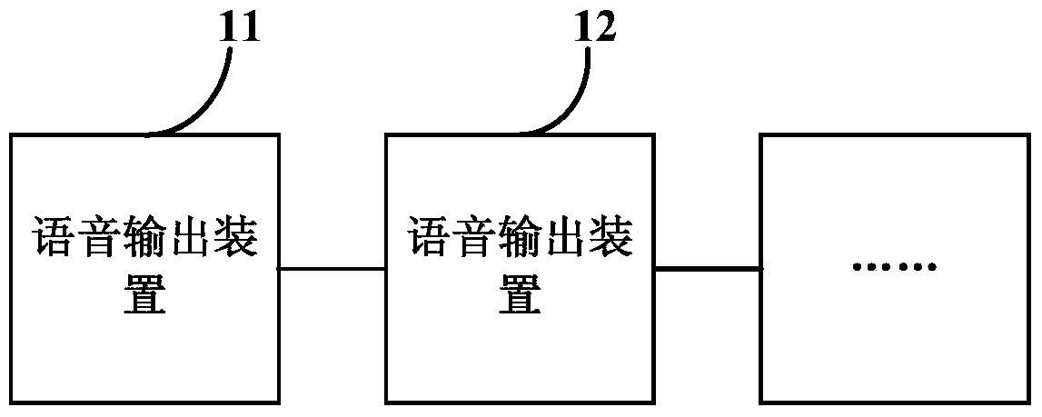
[0022] figure 1 It is a schematic structural diagram of a device for switching a call mode provided in the first embodiment of the present invention. The device can be concentrated in a mobile terminal and used to execute a method for switching a call mode provided in the embodiment of the present invention. Such as figure 1 As shown, the talking mode switching device of this embodiment includes at least two kinds of voice output devices, namely the voice output device 11, the voice output device 12 and so on.

[0023] Wherein, voice switching can be performed among these voice output devices, and each of these voice output devices has advantages and disadvantages, so that the user can choose a voice output device suitable for the scene to make a call according to the scene. For example, if the user is in a noisy place, the voice path can be switched to the voice output device 11 suitable for noisy scenes by inputting a switching command; state, the voice path is switched to...

no. 2 example

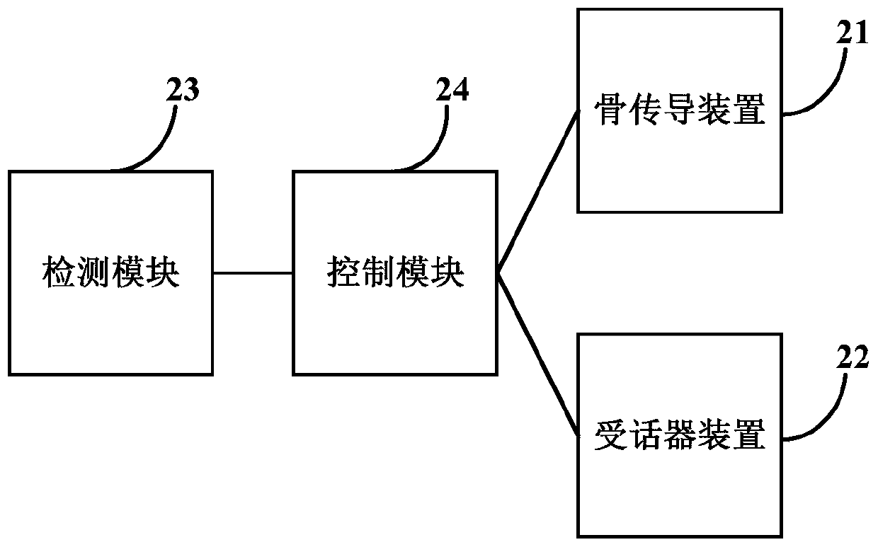
[0039] Figure 2a It is a schematic structural diagram of a talking mode switching device provided by the second embodiment of the present invention. This embodiment is optimized based on the above embodiments. In this embodiment, the voice output device is preferably optimized as a bone conduction device and a receiver device. Such as Figure 2a As shown, the device includes a bone conduction device 21 , a receiver device 22 , a detection module 23 and a control module 24 .

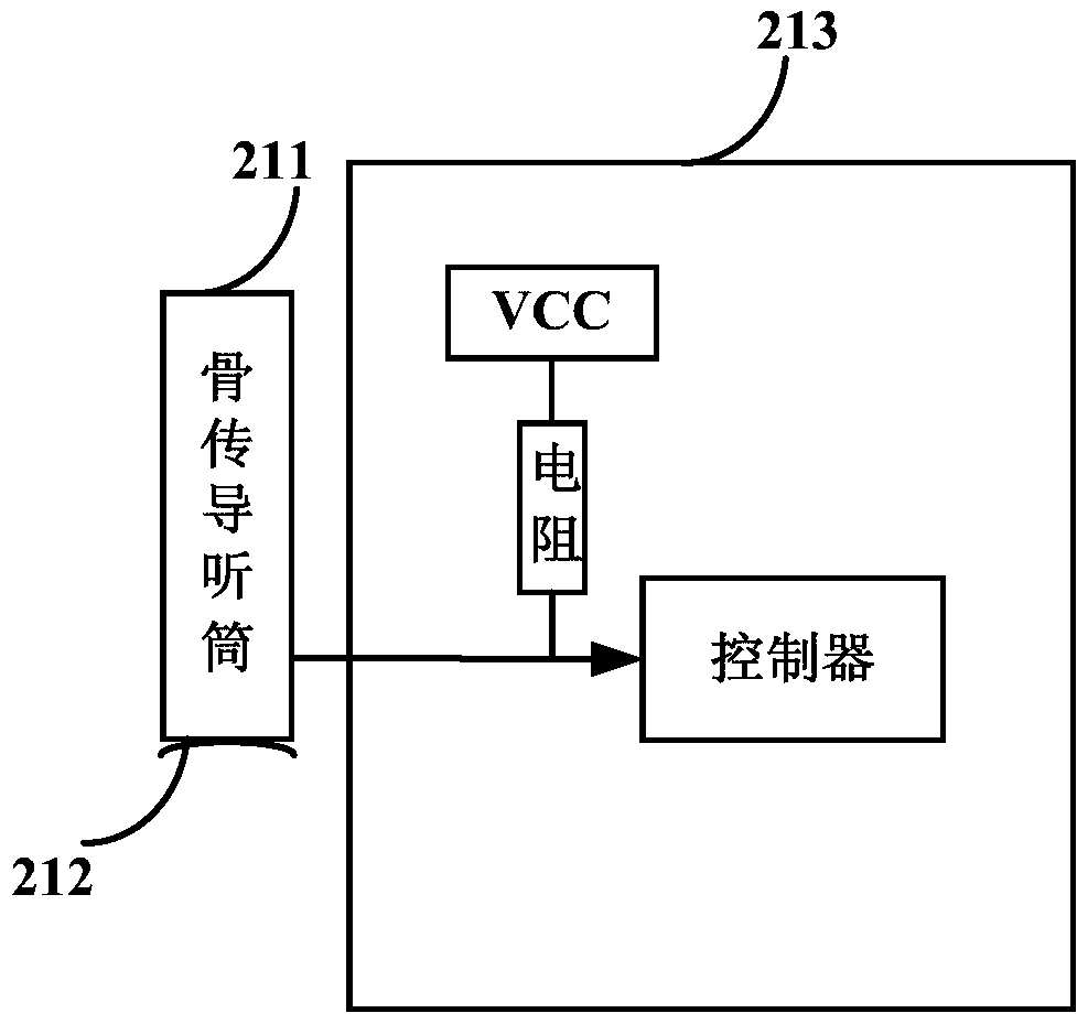
[0040] Wherein, the structural diagram of the bone conduction device 21 is as follows: Figure 2b As shown, it includes a bone conduction earpiece 211, a shrapnel 212 and a detection unit 213, wherein the detection unit 213 is composed of a power supply VCC, a resistor and a controller.

[0041] Combine below Figure 2c Describe in detail the working principle of the device described in this implementation, such as Figure 2c As shown, an audio signal switching circuit such as a switch is provided b...

no. 3 example

[0045] image 3 It is a schematic flow chart of a method for switching a call mode provided by the third embodiment of the present invention, as shown in image 3 As shown, it specifically includes the following steps:

[0046] Step 31: Detecting a switching instruction triggered by the user during the call, and determining that the currently used voice output device is the first voice output device.

[0047] Step 32: Control and cut off the path between the audio circuit and the first voice output device according to the switching instruction, and establish the path between the audio circuit and the second voice output device, so that the second voice output device The audio signal output by the audio circuit is output as voice.

[0048] Exemplarily, on the basis of the above embodiments, the first voice output device is a bone conduction device, and the second voice output device is a receiver voice output device;

[0049] The switching instruction is a pop-in instruction...


PUM


Abstract

The embodiment of the present invention discloses a call mode switching method and device, which are applied to a mobile terminal including at least two voice output devices, wherein the method includes: detecting a switching instruction triggered by a user during a call, and determining the currently used voice The output device is the first voice output device; according to the switching instruction, the path between the audio circuit and the first voice output device is cut off, and the path between the audio circuit and the second voice output device is established, so that the second The voice output device performs voice output according to the audio signal output by the audio circuit. The embodiments of the present invention can meet the user's call requirements in multiple scenarios.

Description

technical field [0001] The embodiment of the present invention relates to mobile communication technology, and in particular to a method and device for switching a calling mode. Background technique [0002] With the continuous development of mobile terminals and science and technology, mobile phone call technology has also been further improved, from traditional receiver mobile terminals to bone conduction mobile terminals. [0003] However, the working principle of the bone conduction mobile terminal is to convert electrical energy into mechanical vibration, and complete the transmission of sound through mechanical vibration, which requires relatively large power consumption, high power consumption, and reduces the battery life of the mobile phone; while the receiver mobile terminal uses The principle of the electromagnetic effect of the inductance, even if the changing audio signal is fed into the voice coil, the voice coil is placed in the magnetic gap of a permanent mag...

Claims


Application Information

Patent Timeline
Patent Type & Authority Patents(China)
IPC IPC(8): H04M1/725
Inventor 曾元清
Owner GUANGDONG OPPO MOBILE TELECOMM CORP LTD
Why Eureka
Try Eureka