Vehicle pneumatic tyre

A technology for pneumatic tires and vehicles, applied in vehicle parts, tire parts, tire treads/tread patterns, etc., can solve the problems of insufficient drainage capacity, water can not be quickly discharged, and can not be fully satisfied, etc., to achieve improvement The effect of water holding capacity

Active Publication Date: 2015-05-13
CONTINENTAL REIFEN DEUTSCHLAND GMBH
View PDF7 Cites 9 Cited by
  • Summary
  • Abstract
  • Description
  • Claims
  • Application Information

AI Technical Summary

Problems solved by technology

In particular in sports tires which are intended for high driving speeds and in many cases have relatively wide tread bands or block rows, the known grooves consisting of two groove segments Can only achieve insufficient drainage capacity
The inability of water to drain from the lugs quickly enough that such tires do not adequately meet the demands placed on them in terms of wet operation (such as wet braking and hydroplaning)

Method used


Image

  • Vehicle pneumatic tyre
  • Vehicle pneumatic tyre
  • Vehicle pneumatic tyre

Examples


Embodiment Construction

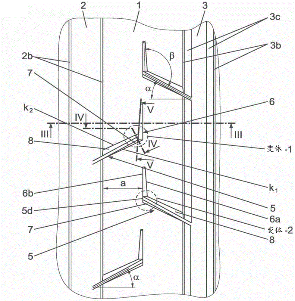
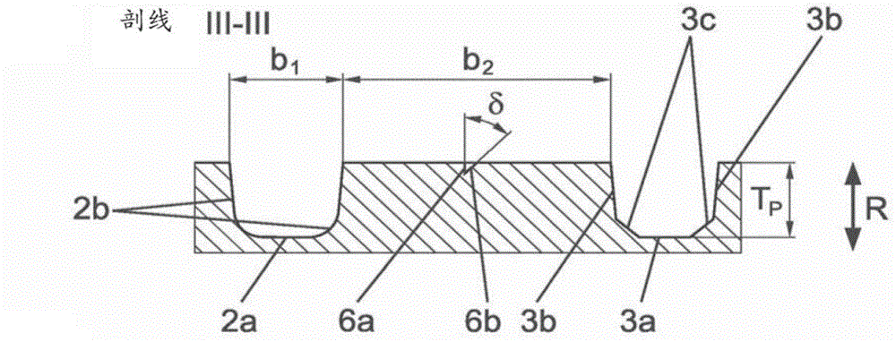
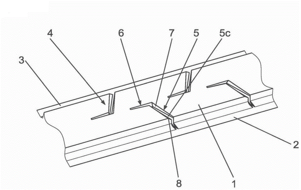
[0024] figure 1 A plan view of a circumferential section of a tread band 1 of the tread of a pneumatic vehicle tire (especially a tire for a passenger car) is shown. The tread of a pneumatic vehicle tire is usually composed of a plurality of convex treads separated from each other by circumferential grooves. These convex treads are either implemented as tread bands or circumferential grooves, or as rows of tread blocks, the latter consisting of It consists of tread blocks that are stacked in the circumferential direction and separated from each other by transverse grooves. in figure 1 The tread band 1 shown in is restricted by one circumferential groove 2, 3 each surrounding the tread in the circumferential direction, wherein the sides of these circumferential grooves 2, 3 can be connected to another structured tread area, For example, the same tread band. Such as especially in figure 2 As shown in the cross-sectional view in, each circumferential groove 2, 3 is restricted by...


PUM


Abstract

The invention relates to a vehicle pneumatic tyre with a tread pattern consisting of profile strips (1) and / or profile block rows. At least one tread lug (1) in which grooves (4) are formed is provided, each groove being composed of two groove sections (5, 6) which extend essentially straight and form an obtuse angle in relation to each other. The first groove section (5) leads into a peripheral groove (2, 3, 3') defining the tread lug (1) and extends forming a maximum angle of 15° with respect to the axial direction and the second groove section (6) extends at least essentially in the peripheral direction and has a shallower depth than the first groove section (5), and it is defined in the cross-section by two groove flanks (6a, 6b) forming a V with respect to each other. The groove flank (6a) facing the peripheral groove (2, 3, 3') extending in the radial direction, and the groove wall of the first groove section (5), facing the second groove section (6) comprise a bevel (7) formed on the longitudinal extension of the groove section (5).

Description

Technical field [0001] The present invention designs a pneumatic vehicle tire with a tread pattern. The tread pattern is divided by a circumferential groove into a convex tread pattern surrounding in the circumferential direction, such as a tread band and / or a tread block row, in which at least A convex tread pattern in which grooves are formed, and these grooves are respectively composed of two groove sections that are at obtuse angles relative to each other and extend substantially linearly, wherein the first groove section merges A circumferential groove that limits the convex tread and extends at an angle of at most 45° with respect to the axial direction and wherein the second groove section extends at least substantially in the circumferential direction. Background technique [0002] For example, EP 2 444 257 A1 discloses a pneumatic vehicle tire of the type mentioned at the beginning. A tire suitable for trucks has a tread pattern consisting of a plurality of tread ribs s...

Claims


Application Information

Patent Timeline
Patent Type & Authority Applications(China)
IPC IPC(8): B60C11/13B60C11/03
CPCB60C11/0309B60C11/13B60C11/1323B60C2011/0369B60C2011/0381
Inventor 乌尔里希·贝尔
Owner CONTINENTAL REIFEN DEUTSCHLAND GMBH
Why Eureka
Try Eureka