Semi-submersible platform with a stabilising fin, and offshore wave power plant incorporating such a platform

A semi-submersible platform, semi-submersible technology, applied in the fields of ocean energy power generation, engine function, engine components, etc., can solve problems such as mechanical fatigue and reduced productivity

Inactive Publication Date: 2015-05-13
若泽·安东尼奥·鲁伊斯迪耶
View PDF0 Cites 7 Cited by
  • Summary
  • Abstract
  • Description
  • Claims
  • Application Information

AI Technical Summary

Problems solved by technology

Similarly, in the case of wave energy plants, platform stability deficiencies can cause erratic movement of the power mechanism, leading to mechanical fatigue and reduced productivity

Method used


Image

  • Semi-submersible platform with a stabilising fin, and offshore wave power plant incorporating such a platform
  • Semi-submersible platform with a stabilising fin, and offshore wave power plant incorporating such a platform
  • Semi-submersible platform with a stabilising fin, and offshore wave power plant incorporating such a platform

Examples


Embodiment Construction

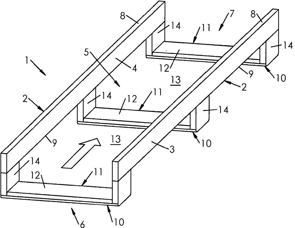
[0039] exist figure 1 The semi-submersible floating platform 1 is shown above, and the semi-submersible floating platform is used as an infrastructure for marine engineering facilities, such as wind power plants, which are equipped with one or more wind turbines, and the Offshore installations or even wave energy plants, as will be seen in the examples described below. Two types of power stations, one wind power station and the other wave power station, can be jointly installed on the platform 1 .

[0040] The platform 1 comprises a plurality of elongated buoyant tanks 2 arranged substantially parallel in a longitudinal direction corresponding to the main direction of surge of the swell when the platform 1 is located at sea (in figure 1 indicated by an arrow).

[0041] In the example, the number of these pontoons 2 is two, the pontoons have the shape of a parallelepiped with a square or (as indicated) rectangular cross-section, the height of the pontoons is preferably greate...


PUM


Abstract

A semi-submersible platform (1) comprising: - at least two longitudinal boxes (2), the boxes (2) having solid side walls (3, 4) delimiting a central channel (5) which extends from a bow end (6) to a stern end (7) of the platform (1); - at least one beam (10) transversely coupling the boxes (2); - at least one stabilising fin (11) which extends transversely beyond the lower edges (9) of the boxes (2).

Description

technical field [0001] The present invention relates to a semi-submersible platform for offshore installation and as a foundation structure for floating installations. Background technique [0002] Floating facilities, such as wind power plants or wave power plants (i.e. using surges to generate energy), require the platform supporting the floating facilities to be not only rigid but also stable, which naturally presents difficulties due to surges, Swells tend to impart alternating longitudinal (pitch) and lateral (roll) rotational motion to any floating structure. [0003] These movements are to be avoided because of the negative effects they imply for the installation: fatigue (and thus wear) of the mechanical components, reduced efficiency. In the case of wind turbines, rolling and pitching motions are detrimental to their proper operation, since the masts are then subjected to high bending stresses, and moreover the wind turbines are often deviated with respect to the w...

Claims


Application Information

Patent Timeline
Patent Type & Authority Applications(China)
IPC IPC(8): B63B35/44F03B13/18
CPCB63B2035/4466F03B13/1815F05B2260/406B63B35/44Y02E10/30B63B1/10B63B1/107B63B1/121F03B13/16
Inventor 若泽·安东尼奥·鲁伊斯迪耶
Owner 若泽·安东尼奥·鲁伊斯迪耶
Why Eureka
Try Eureka