Miniature anchorage screw and correcting device with same

An anchorage nail and a miniature technology are applied in the field of miniature anchorage nails and orthodontic devices containing the mini anchorage nails, and can solve the problems of circumferential displacement of anchorage nails, poor release of traction force, and reduced effectiveness of orthodontic correction, etc. Achieve the effect of improving circumferential stability and avoiding bad release

Active Publication Date: 2015-05-20
杭州西湖生物材料有限公司
View PDF7 Cites 9 Cited by
  • Summary
  • Abstract
  • Description
  • Claims
  • Application Information

AI Technical Summary

Problems solved by technology

[0011] However, analyzing the structure of the orthodontic miniature self-tapping anchorage nail in the prior art, it is found that there are still the following disadvantages: after the anchorage nail is actually implanted into the compact bone, orthodontic traction is started, and the teeth are pulled together with arch wires and brackets. Connect with the anchorage nail, take t...

Method used


Image

  • Miniature anchorage screw and correcting device with same
  • Miniature anchorage screw and correcting device with same
  • Miniature anchorage screw and correcting device with same

Examples


Embodiment 2

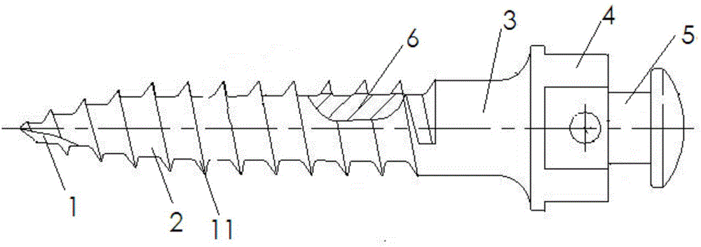
[0049] The second embodiment is: the circumferential stabilizing grooves 6 are arranged on the tooth forms 8 , 9 , 10 and 11 .

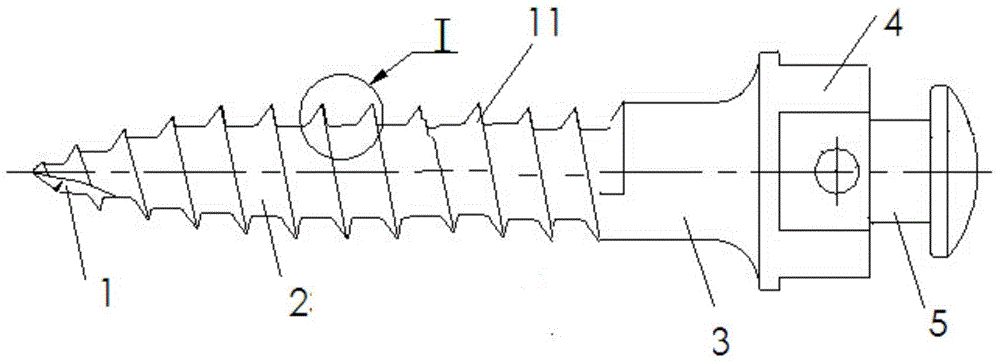
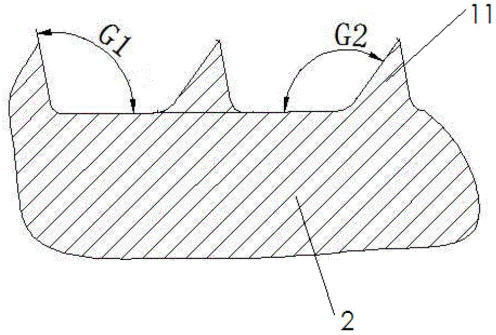
[0050] Certainly, the number of tooth-shaped bodies 11 that screw body 2 is provided with from the top to the tail end is not unique, and can be adjusted as required. Similarly, the position of circumferential stabilizing groove 6 can also be adjusted according to the length of screw body 2, but Always at the tail end of the screw body 2.

[0051] Example 1: The screw main body 2 is provided with 10 conodonts 11 from the top end to the tail end, named respectively as conodonts 1, 2, 3, 4, 5, 6 and 7. , Conodont 8, Conodont 9, and Conodont 10. For the first embodiment, the circumferential stabilizing groove 6 is arranged on the tooth form 8, the tooth form 9 and the tooth form 10;

[0052] Example 2: The screw main body 2 is provided with 12 conodonts 11 from the top end to the tail end, named respectively as conodonts 1, 2, 3, 4, 5, 6 and 7. , Con...

Embodiment 1

[0066] If the first cavity wall 7 actually has the number of effective thread teeth N=3,

[0067] Then the average small first cavity wall 7 on each conodont 11 bears a force f N =F N / 3=180 / 3=60 grams.

[0068] Assume that the helix angle ∠W=68.04° in this embodiment (according to the M2.0 anchor screw, here is not measured by the diameter of the pitch circle for the time being)

[0069] Then the small first cavity wall 7 on each conodont 11 is stressed:

[0070] f P = f N *SIN∠W=60*SIN68.04=55.65 grams

[0071] f S = f N *COS∠W=60*COS68.04=22.44 grams

[0072] shear stress f N The component forces on the first cavity wall 7 and in the normal direction perpendicular to the first cavity wall 7 are respectively f P and f S , in other words, f P The small first cavity wall 7 on each conodont 11 supports the effective shearing force on the compact bone when the nail is subjected to the maximum torque.

[0073] set f w is the shear strength of the implanted part of t...

Embodiment 2

[0076] If the actual effective thread thread number N=4 of the first chamber wall 7,

[0077] Then the average small first cavity wall 7 on each conodont 11 bears a force f N =F N / 4=180 / 4=45 grams.

[0078] Assume that the helix angle ∠W=68.04° in this embodiment (according to the M2.0 anchor screw, here is not measured by the diameter of the pitch circle for the time being)

[0079] Then the small first cavity wall 7 on each conodont 11 is stressed:

[0080] f P =f N *SIN∠W=45*SIN68.04=41.74 grams

[0081] f S =f N *COS∠W=45*COS68.04=16.82 grams

[0082] shear stress f N The component forces on the first cavity wall 7 and in the normal direction perpendicular to the first cavity wall 7 are respectively f P and f S , in other words, f P The small first cavity wall 7 on each conodont 11 supports the effective shearing force on the compact bone when the nail is subjected to the maximum torque.

[0083] set f w is the shear strength of the implanted part of the com...


PUM

PropertyMeasurementUnit
Helix angleaaaaaaaaaa

Abstract

The invention discloses a miniature anchorage screw and a correcting device with the same. A circumferential stabilizing groove is formed in a screw rod main body and is arranged in the tail end of the screw rod main body. The circumferential stabilizing groove comprises a first cavity wall, a second cavity wall and a cavity formed by the first cavity wall and the second cavity wall; the surface where the first cavity wall of the circumferential stabilizing groove is located is vertical to the surface where a threaded guide of the screw rod main body is located; the length of the cavity is equal to the distance among 3-4 tooth-shaped bodies, and the depth of the cavity is equal to the height of a tooth; the first cavity wall and the screw rod main body form a rotary cutting angle; and the rotation direction of the rotary cutting angle is opposite to the implanting rotation direction of the screw rod main body. After the anchorage screw is implanted to a gum, a compact bone grows to fill the circumferential stabilizing groove, so that the implanted miniature anchorage screw obtains a resistance surface along the tangential direction of a circumference, and the phenomenon of circumferential rotary displacement of the implanted miniature anchorage screw is avoided. By using the miniature anchorage screw, the circumferential stability of the miniature anchorage screw can be improved, and the condition that the deformity collecting effect is reduced because of harmful release of a traction force is avoided.

Description

technical field [0001] The invention belongs to the technical field of orthodontic equipment, and in particular relates to a miniature anchorage nail and an orthodontic device containing the miniature anchorage nail. Background technique [0002] Orthodontics is the treatment of malocclusion of teeth through surgery or orthodontic equipment. Surgical treatment of dental malocclusion is expensive, recovery is slow, and the curative effect is not good, so most patients with dental malocclusion will choose to wear orthodontic equipment to correct dental malocclusion. As one of the commonly used orthodontic devices, micro-anchor nails are widely used. [0003] Traditional micro-anchor nails are divided into cylindrical and conical according to the shape of the implanted part. The implantation process mainly includes the following steps: first make a mucosal incision of several millimeters long at the designed position, then use a suitable drill to open a guide hole in the expo...

Claims


Application Information

Patent Timeline
IPC IPC(8): A61C7/00
Inventor 茹栋韩天鹏王国庆陈利华狄传亮
Owner 杭州西湖生物材料有限公司
Why Eureka
Try Eureka