Cryostat having a reinforced interior vessel

a technology of cryostats and internal vessels, applied in the field of cryostats, can solve the problems of large metrological challenge, large changes in the magnetic field temporal, and easy appearance of changes,

Inactive Publication Date: 2011-02-17
BMDSYS PRODN
View PDF0 Cites 1 Cited by
  • Summary
  • Abstract
  • Description
  • Claims
  • Application Information

AI Technical Summary

Benefits of technology

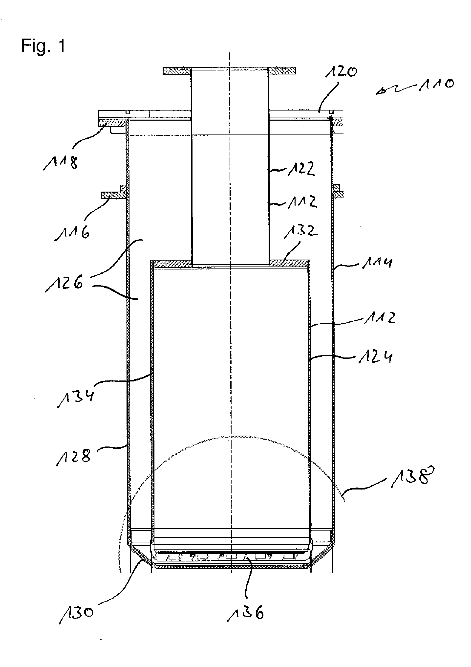
[0014]The inner vessel has a base part and a sidewall connected to the base part in a circumferential connection region. This modular design was found to be advantageous over integral designs because this already affords the possibility of avoiding much of the tension in the transition region between the base and the sidewalls.
[0017]By contrast, the proposed strengthening element with the fibers of the fibrous material oriented in the circumferential direction acts like a “strengthening belt” and said element is based on the same basic idea as, for example, a radial tire in automotive technology. The individual fibers of the fibrous material can be interlocking and so the stability of the circumferential strengthening material is additionally increased in the radial direction over outwardly running loads.
[0018]This can greatly reduce the above-described problems relating to the quality and stability of the inner vessel in the particularly critical connection region between the base part and the sidewall. There is no noteworthy damage or wear and tear in this region, even after a multiplicity of evacuation processes.
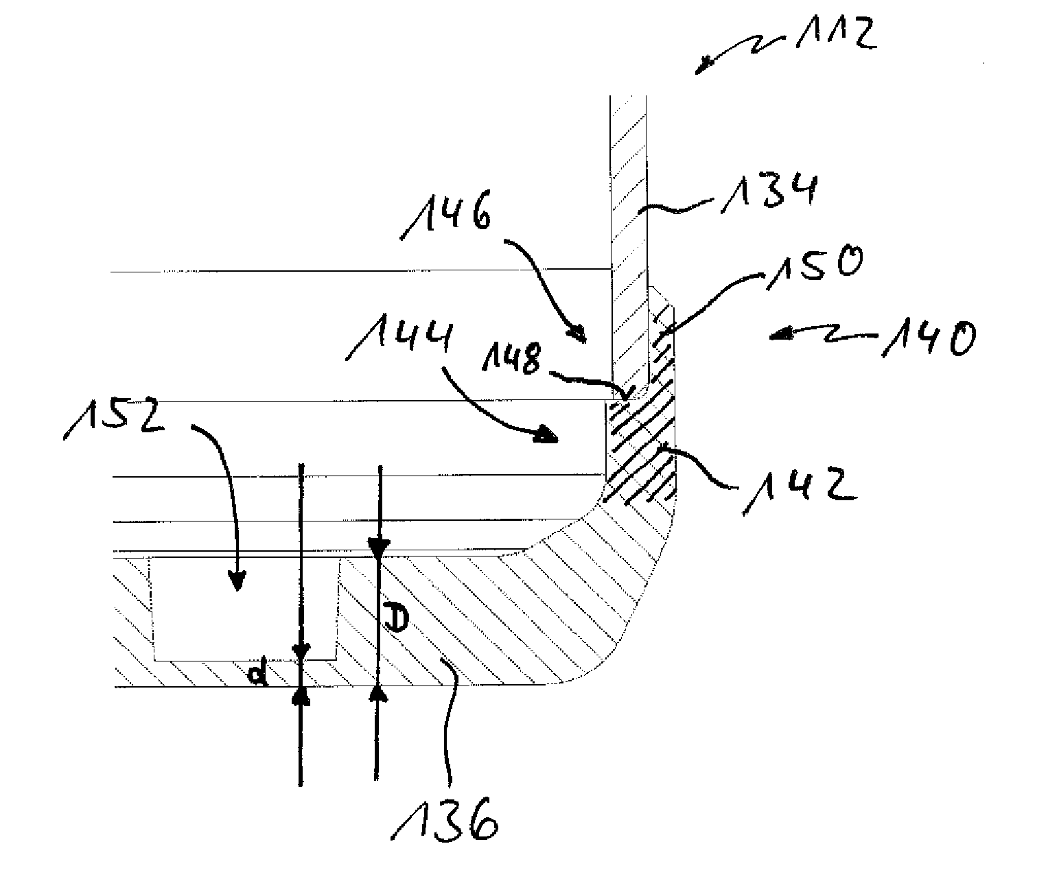
[0023]As described above, the base part can have an elevated edge, with the edge being oriented substantially parallel to the sidewall. The strengthening element can be an integral component of this elevated edge; for example, it can be an upper region of this elevated edge. As described above, this elevated edge, particularly in the region of the strengthening element, moreover can have a step, with a lower step surface pointing into the interior of the inner vessel. The sidewall can be supported on this lower step surface. By way of example, this makes it possible for the lower region of the sidewall to be enclosed by an elevated ring or collar of the step. It is particularly preferred in this case if this elevated ring of the step, which surrounds the sidewall, contains the strengthening elements.
[0025]In particular, the first fibrous material and / or possibly the second fibrous material as well can have at least one of the following fibrous materials: a glass-fiber material, a carbon-fiber material, a mineral-fiber material. Combinations of these and / or other materials are also possible. As illustrated above, it is particularly preferable for the fibrous material to have a multiplicity of interlocking fibers in the process. It is particularly preferred if the fibrous material comprises at least one fiber mat, which for example can contain fibers oriented substantially in parallel, even with deviations of not more than preferably 10°-20° from parallel still being tolerable. By way of example, this fiber mat then can have an elongate shape, for example the shape of an elongate strip, wherein the fibers then preferably are arranged in parallel to the longitudinal extent of this strip. The fiber mat should extend at least once over the circumference of the strengthening element, with it being particularly preferable for this fiber mat reach around this circumference a number of times. In this case, a winding technique can be used and this can result in a particularly stable strengthening element.
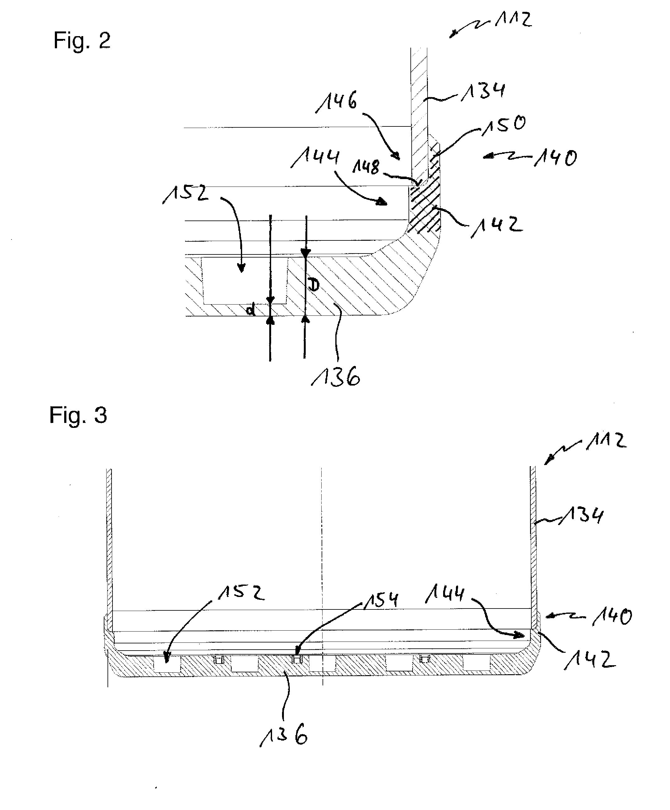
[0036]Moreover, for serial use, it is preferred if a multiplicity of different base parts, which can be used for different types of sensors, can be provided for the inner vessel. By way of example, different sensors can be used, which require a respectively different distance from the skin surface of a patient. However, in conventional methods, this modular technique would mean that a new mold would have to be constructed for each sensor system with different sensors, which is connected with significant costs. In order nevertheless to be able to implement the fiber technique described above in a cost-effective manner and also afford the production of a “modular system” for different sensors in the case of the proposed, qualitatively very stable cryostat, it is therefore proposed to generate the recesses for holding the biomagnetic sensors such that the mold has a multiplicity of interchangeable cores. These cores can have the desired negative shape in respect of the recesses and their selection can be made depending on the desired depth of the recesses. This also affords producing cryostats for a multiplicity of sensors in large-scale serial use, which sensors nevertheless have the above-described positive quality properties.

Problems solved by technology

However, measuring the magnetic fields of biological samples or patients, or measuring temporal changes in these magnetic fields constitutes a large metrological challenge.
Thus, detecting these changes requires extremely sensitive magnetic sensors.
It is a big challenge in terms of the design to produce the cryostat for holding biomagnetic sensor systems.
However, the conventional cryostats used for magnetic measurements in practice have a multiplicity of disadvantages and difficulties, which can have an effect on the reliability and reproducibility of the measurements.
In addition it has been shown that distortions can easily appear, particularly in the transition region between the base part and the sidewall of the inner vessel, and these distortion can cause cracks, which in turn can have a strong negative influence on the quality of the cryostat.

Method used


Image

  • Cryostat having a reinforced interior vessel
  • Cryostat having a reinforced interior vessel
  • Cryostat having a reinforced interior vessel

Examples


Embodiment Construction

[0011]This object is achieved by a cryostat and a method for producing a cryostat with the features of the independent claims. Advantageous developments of the invention, which can be implemented on their own or can be combined, are illustrated in the dependent claims. The wording of all claims is hereby incorporated in the description by reference.

[0012]A cryostat for use in a biomagnetic measurement system is proposed, which cryostat has at least one inner vessel and at least one outer vessel, and at least one cavity arranged between the inner vessel and the outer vessel. Provision can analogously be made for a plurality of such inner and / or outer vessels and / or a plurality of cavities. Negative pressure should be able to be applied to the cavity, that is to say it should be possible to seal said cavity in order to make it possible to evacuate it. For this purpose, the inner and outer vessel for example can have appropriate seals (for example separate sealing rings and / or sealing ...


PUM

PropertyMeasurementUnit
biomagneticaaaaaaaaaa
pressureaaaaaaaaaa
circumferenceaaaaaaaaaa

Abstract

A cryostat (110) for use in a biomagnetic measurement system is proposed. The cryostat (110) comprises at least one inner vessel (112) and at least one outer vessel (114), and at least one cavity (126) arranged between the inner vessel (112) and the outer vessel (114), in which negative pressure can be applied to the cavity (126). The inner vessel (112) has a base part (136) and a sidewall (134) connected to the base part (136) in a circumferential connection region (140). The inner vessel (112) has a circumferential strengthening element (142) in the connection region (140), with the strengthening element (142) having a first fiber composite material with a first fibrous material (158) with an anisotropic orientation and with a local preferred orientation, the local preferred orientation being oriented substantially in the circumferential direction of the cryostat (110).

Description

FIELD OF THE INVENTION[0001]The invention relates to a cryostat particularly suitable for use in a biomagnetic measurement system and a biomagnetic measurement system comprising such a cryostat. The invention furthermore relates to a method for producing a cryostat particularly suitable for biomagnetic measurements. Such cryostats and measurement systems can be used, in particular, in the field of cardiology, or else in other fields of medicine, such as neurology. Other applications, for example non-medical applications, for example applications in materials science, are also feasible.PRIOR ART[0002]In recent years and decades, magnetic measurement systems, which were previously restricted in essence to use in basic research, found their way into many areas of the biological and medical sciences. Neurology and cardiology in particular profit from such biomagnetic measurement systems.[0003]Biomagnetic measurement systems are based on most cell activities in the human or animal body b...

Claims


Application Information

Patent Timeline
Patent Type & Authority Applications(United States)
IPC IPC(8): F17C3/08F17C1/16B27N3/14G01R33/02
CPCF17C3/085F17C2201/0119F17C2203/0391F17C2203/0665F17C2270/0509F17C2205/0111F17C2221/017F17C2223/0161F17C2270/02F17C2203/0673
Inventor NOWAK, HANNESERNE, SERGIO NICOLA
Owner BMDSYS PRODN
Why Eureka
Try Eureka