Multi-combined-station automatic core making center

An automatic manufacturing and station technology, applied in the direction of manufacturing tools, metal processing equipment, casting molding equipment, etc., can solve the problems affecting the quality of finished products, sand core damage, difficulties, etc., to reduce production costs, avoid damage to sand cores, reduce The effect of labor intensity

Active Publication Date: 2015-05-20
刘晓桐
View PDF13 Cites 12 Cited by
  • Summary
  • Abstract
  • Description
  • Claims
  • Application Information

AI Technical Summary

Problems solved by technology

However, during the core-pulling process, since the two core-shooting half-open molds slide outward respectively, the horizontal position of the shaped sand core cannot be fixed, and the randomness is very large, and it may be separated from the two core-shooting half-open molds. Open free fall, also possible with one of the two core-shooting half-open dies still connected
This kind of position cannot be fixed, which brings great difficulties to the core pulling work, and it is easy to cause the well-shaped sand core to fall, and the staff cannot catch it in time, resulting in damage to the sand core, which seriously affects the quality of the finished product
In addition, the existing core shooter can only produce sand cores of one model, and the amount of sand injected into the model at one time is limited. If another model of sand core is produced, it is necessary to replace the parts of the machine, such as the core shooter The box and the corresponding sand shooting mechanism, the replacement of parts brings inconvenience to the production and is easy to damage the parts

Method used


Image

  • Multi-combined-station automatic core making center
  • Multi-combined-station automatic core making center
  • Multi-combined-station automatic core making center

Examples


Embodiment Construction

[0031]Below in conjunction with accompanying drawing and embodiment, further elaborate the present invention. In the following detailed description, certain exemplary embodiments of the invention are described by way of illustration only. Needless to say, those skilled in the art would realize that the described embodiments can be modified in various different ways, all without departing from the spirit and scope of the present invention. Accordingly, the drawings and description are illustrative in nature and not intended to limit the scope of the claims.

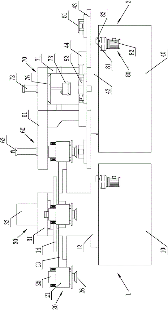
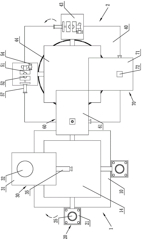
[0032] like figure 1 and figure 2 As shown, the multi-combination station automatic core-making center includes a sand-shooting rotary working device 1 and a core mold rotary working device 2 that cooperate with each other, and the sand-shooting rotary working device 1 and the core mold rotary working device 2 respectively correspond to A rotary drive mechanism 80 is provided;

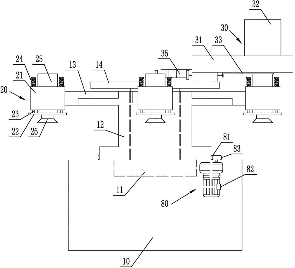
[0033] like image 3 , Figure 4 and ...


PUM


Abstract

The invention discloses a multi-combined-station automatic core making center. The automatic core making center comprises a sand jetting rotary working device and a core model rotary working device, wherein the sand jetting rotary working device comprises a sand jetting rotary seat; a plurality of sand jetting worktables are arranged on the peripheral side above the sand jetting rotary seat; a sand jetting mechanism is arranged on each sand jetting worktable; a sand storage mechanism is supported on the top of the sand jetting supporting seat; the core model rotary working device comprises a core model rotary seat; a plurality of core model worktables with the amount which corresponds to the amount of the sand jetting worktables are arranged on the peripheral side of the core model rotary seat; a core jetting mold matched with the sand jetting mechanism is arranged on each core model worktable; and a sand blowing mechanism is supported on the upper side of the core model supporting seat. By utilizing the automatic core making center, the production of sand cores of a plurality of models can be performed at the same time, the sand receiving, sand jetting, fixing and core pulling processes can be performed at the same time, and meanwhile, the sand cores are effectively prevented from falling during the sand pulling process.

Description

technical field [0001] The invention relates to a casting machine, in particular to a core shooting machine. Background technique [0002] The core shooting machine used in the foundry industry now generally uses a single station for mold molding operations, which is carried out by one or two operators, and a series of processes such as sand shooting, shaping, and core pulling are completed at this station. The equipment leads to low production efficiency, high labor intensity and high equipment cost. In addition, most of the existing core shooting machines adopt the form of split-type mold opening, that is, two core-shooting half-opening molds are used to slide relatively. The outer sides of the two core-shooting half-opening molds are respectively connected with horizontal clamping cylinders. The horizontal clamping cylinder acts to control the closing of the two core-shooting half-open molds to carry out the sand-shooting process, and controls the separation of the two c...

Claims


Application Information

Patent Timeline
Patent Type & Authority Applications(China)
IPC IPC(8): B22C15/23
CPCB22C15/23
Inventor 刘晓桐
Owner 刘晓桐
Why Eureka
Try Eureka