Winding mould mechanism for winding machine

A winding die and winding machine technology, applied in the direction of electromechanical devices, manufacturing motor generators, electrical components, etc., can solve the problems of wasting wires, increasing production costs for manufacturers, reducing production efficiency, etc., to reduce investment and avoid frequent The effect of replacing and reducing labor intensity

Inactive Publication Date: 2012-09-19
NIDE MECHANICAL EQUIP
View PDF0 Cites 11 Cited by
  • Summary
  • Abstract
  • Description
  • Claims
  • Application Information

AI Technical Summary

Problems solved by technology

[0004]However, as mentioned above, since the distance between the upper and lower molds is fixed (installed on the mold base together, connected by the mold base and the turntable), Depending on the power of the three-phase motor, it is necessary to replace the winding dies of different sizes to meet the requirements of the coil diameter. Therefore, on the one hand, repeated replacement of the winding dies not only reduces the production efficiency, but also increases the labor intensity; on the other hand, it is necessary to Prepare winding dies of different sizes to meet production needs. Inaccurate sizes w

Method used


Image

  • Winding mould mechanism for winding machine
  • Winding mould mechanism for winding machine
  • Winding mould mechanism for winding machine

Examples


Embodiment 1

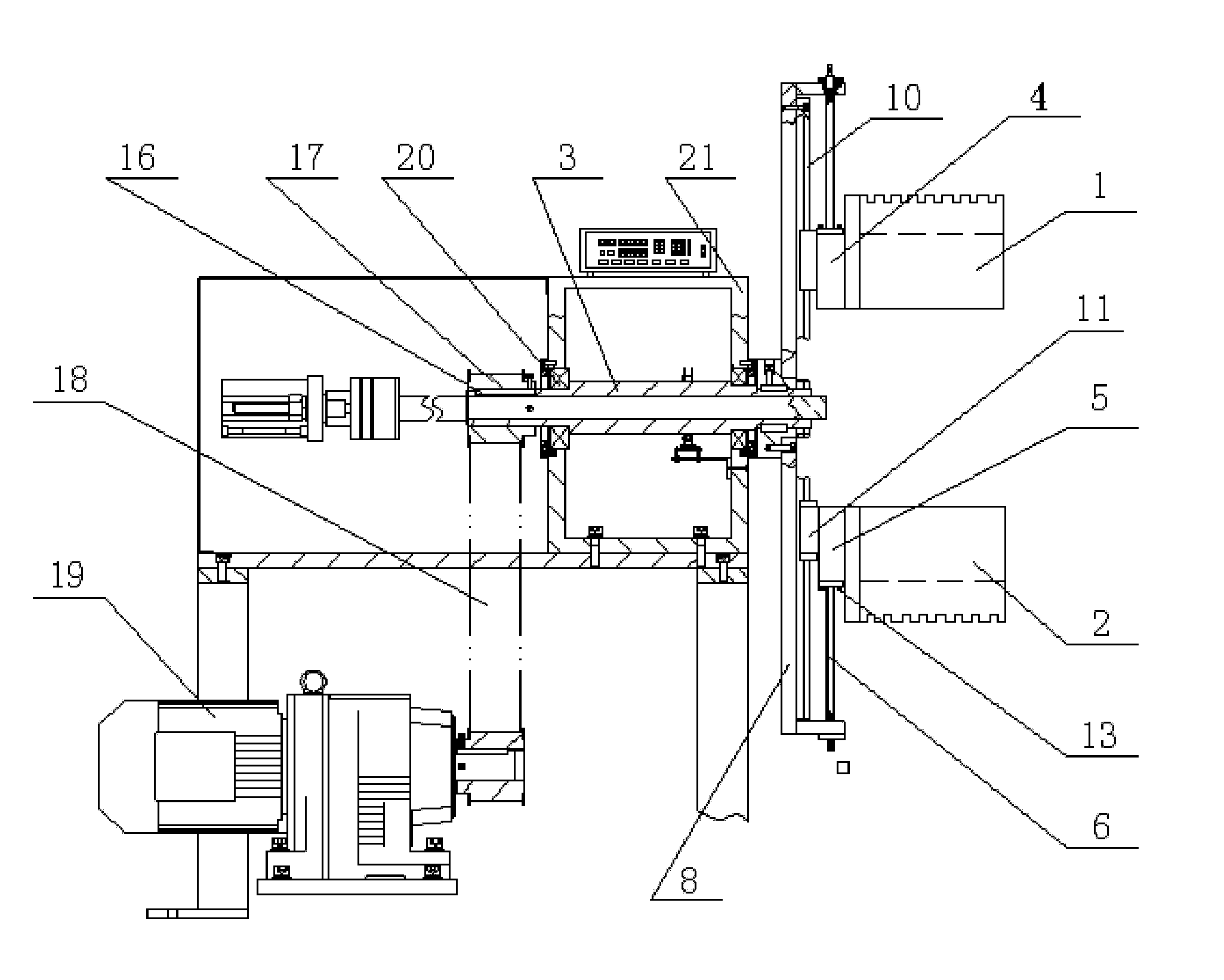
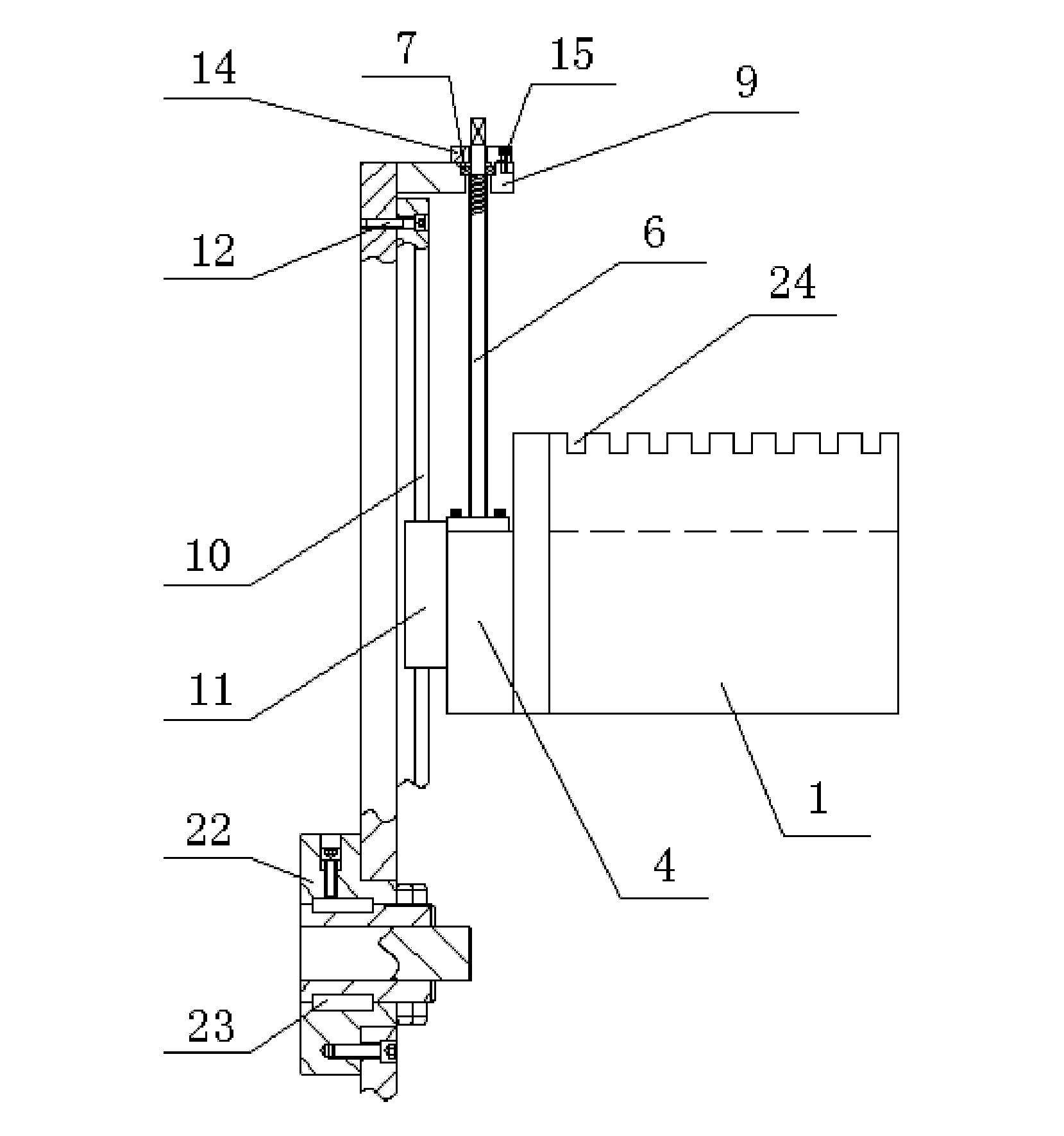
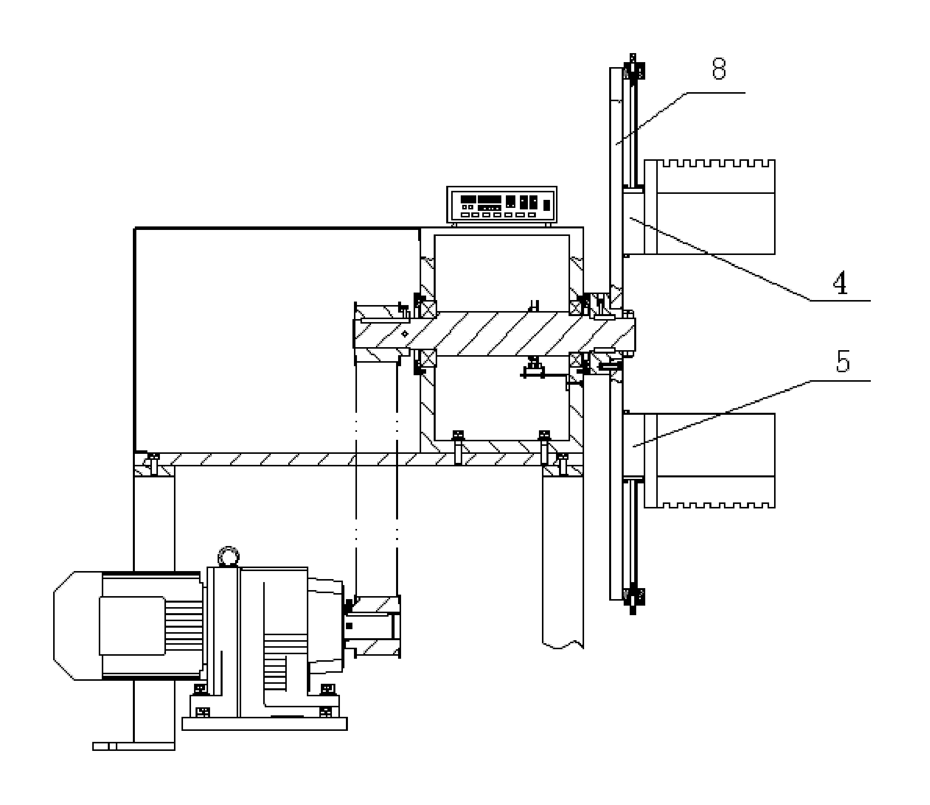
[0018] Embodiment one: see Figure 1~2 As shown, a winding mold mechanism of a winding machine includes 1 upper mold and 2 lower molds, the upper mold 1 and the lower mold 2 are arranged symmetrically with the center of the rotating spindle 3, and the upper mold 1 is installed On an upper base 4, the lower mold 2 is installed on the lower base 5, and an adjusting screw 6 is screwed on the outside of each base, and the outer end of each adjusting screw 6 passes through a bearing 7 It is connected with the screw mounting seat 9 on the turntable 8 of the winding machine, the upper base 4 and the lower base 5 are respectively slidably connected to the turntable 8 of the winding machine through a guide mechanism, and the adjusting screw 6 and The direction of extension of the guiding mechanism is perpendicular to said rotating spindle 3 .

[0019] Such as figure 2 As shown, the guide mechanism is composed of a guide rod 10 and two sliders 11 slidably connected to the guide r...

Embodiment 2

[0021] Embodiment two: see Figure 3-4 As shown, a winding mold mechanism of a winding machine, in this embodiment, the structure is basically the same as that of Embodiment 1, the difference is that the guide mechanism is a guide card set on the turntable 8 of the winding machine Slots 25 , the upper base 4 and the lower base 5 are provided with protrusions that match with the guide slots, and are slid into the corresponding guide slots 25 . The guide slot 25 is a dovetail slot. On the one hand, it provides guidance, and on the other hand, it also provides positioning for the upper base 4 and the lower base 5, so as to avoid deviating from the guide slot 25 .


PUM


Abstract

The invention discloses a winding mould mechanism for a winding machine. The winding mould mechanism comprises an upper mould and a lower mould which are in central symmetry about a rotating spindle. The winding mould mechanism is characterized in that the upper mould is mounted on an upper base, the lower mould is mounted on a lower base, the outside of each base is connected with an adjusting screw rod in a threaded manner, the outer end of each adjusting screw rod is connected with a screw rod mounting seat positioned on a rotary table of the winding machine through a bearing, the upper base and the lower base are respectively slidably connected on the rotary table of the winding machine through a guide mechanism, and the extension direction of each adjusting screw rod and the guide mechanism is perpendicular to the rotating shaft. The adjusting screw rods are connected with the upper base and the lower base positioned at the bottoms of the upper mould and the lower mould respectively in a threaded manner, so that the distance between the upper mould and the lower mould is adjusted, the requirements of various stator coils on winding are met, and the utilization rate of the winding machine is increased.

Description

technical field [0001] The invention relates to an induction coil winding machine, in particular to a winding mold mechanism of the winding machine, which is mainly used for winding stator coils of high-power three-phase motors. Background technique [0002] Three-phase motor means that when the three-phase stator windings of the motor (each with a phase difference of 120 degrees of electrical angle), a rotating magnetic field will be generated after the three-phase alternating current is connected, and the rotating magnetic field will cut the rotor winding, thereby generating an induced current in the rotor winding (rotor The winding is a closed path), and the current-carrying rotor conductor will generate electromagnetic force under the action of the rotating magnetic field of the stator, thereby forming an electromagnetic torque on the motor shaft, driving the motor to rotate, and the direction of rotation of the motor is the same as that of the rotating magnetic field. ...

Claims


Application Information

Patent Timeline
IPC IPC(8): H02K15/04
Inventor 李胜权
Owner NIDE MECHANICAL EQUIP
Why Eureka
Try Eureka