Transmission type plate shearing machine

A shearing machine, transmission type technology, applied in shearing machine equipment, shearing device, metal processing equipment and other directions, can solve the problems of long transmission time, long transmission distance, short service life, etc., to shorten the transmission time and work efficiency. Improve and improve the effect of production efficiency

Inactive Publication Date: 2015-05-20
华国洋
View PDF6 Cites 4 Cited by
  • Summary
  • Abstract
  • Description
  • Claims
  • Application Information

AI Technical Summary

Problems solved by technology

Before the shearing machine was invented, such cutting work generally used saw blades or other non-professional mechanical equipment. Such a method could not guarantee the processing quality, but also had no processing benefits; while the existing shearing machine , in order to achieve the highest precision size cutting, a large number of electronic components are used. Due to the relationship between their own materials and perfo

Method used


Image

  • Transmission type plate shearing machine

Examples


Example Embodiment

[0011] The preferred embodiments of the present invention will be described in detail below with reference to the accompanying drawings, so that the advantages and features of the present invention can be more easily understood by those skilled in the art, so as to make a clearer and clearer definition of the protection scope of the present invention.

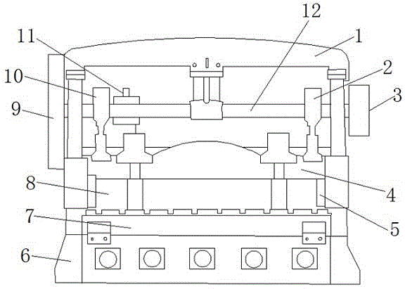
[0012] Such as figure 1 As shown, a transmission type shearing machine includes a beam 1, and a main shaft 12 arranged below the beam 1, and a reducer 3 arranged on the right end of the main shaft 12, and a gear 9 arranged on the left end of the main shaft 12, and The connecting rod 2, the flywheel 10, and the motor 11 on the main shaft 12, and the upper tool holder 4 arranged below the main shaft 12, and the material press 8 arranged below the upper tool holder 4, and the end of the material press 8 The guide groove 5, and the lower tool holder 7 provided under the presser 8, and the frame 6 provided below the lower tool holder 7...


PUM


Abstract

The invention provides a transmission type plate shearing machine. The plate shearing machine comprises a crossbeam, a main shaft arranged under the crossbeam, a reducer arranged at the right end of the main shaft, a gear arranged at the left end of the main shaft, a connecting rod, a flywheel, an electric motor, an upper tool carrier arranged under the main shaft, an eccentric swage arranged under the upper tool carrier, guiding grooves arranged in the end of the eccentric swage, a lower tool carrier arranged under the eccentric swage, and a rack arranged under the lower tool carrier; the flywheel is located on the right side of the gear; wherein the connecting rod, the flywheel, and the electric motor are arranged on the main shaft; the electric motor is located on the right side of the flywheel; the connecting rod is located on the left side of the reducer. The transmission type plate shearing machine has the advantages that the processing benefit is high, the processing quality is good, and the service life is long.

Description

technical field [0001] The invention relates to a transmission type shearing machine. Background technique [0002] The shearing machine is a kind of forging machinery, and its main function is the metal processing industry. Products are widely used in aviation, light industry, metallurgy, chemical industry, construction, shipbuilding, automobile, electric power, electrical appliances, decoration and other industries. Especially now that the construction industry and decoration industry are developing very fast, people attach great importance to the living environment, so the shearing machine is used by more people. The main function of the shearing machine is to cut metal sheets of various thicknesses, so that the sheets can be broken and separated according to the required size. Before the shearing machine was invented, such cutting work generally used saw blades or other non-professional mechanical equipment. Such a method could not guarantee the processing quality, but...

Claims


Application Information

Patent Timeline
IPC IPC(8): B23D15/06
Inventor 华国洋
Owner 华国洋
Why Eureka
Try Eureka