Electrolytic machining device

A processing device and electrolytic cell technology, which is applied in the direction of electric processing equipment, electrochemical processing equipment, processing electrodes, etc., can solve the problems of inability to effectively discharge deep cavity electrolysis products, etc.

Active Publication Date: 2015-05-20
富联精密电子(郑州)有限公司
View PDF5 Cites 11 Cited by
  • Summary
  • Abstract
  • Description
  • Claims
  • Application Information

AI Technical Summary

Problems solved by technology

However, when processing deep cavities, the electrode vibration ca...

Method used


Image

  • Electrolytic machining device
  • Electrolytic machining device
  • Electrolytic machining device

Examples


Embodiment Construction

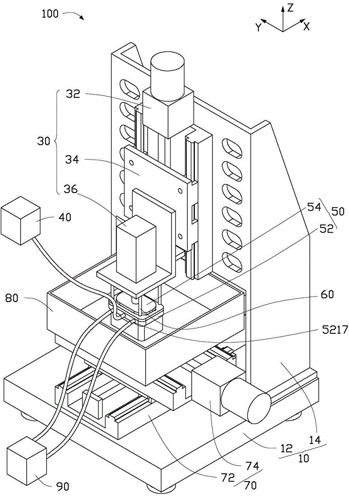
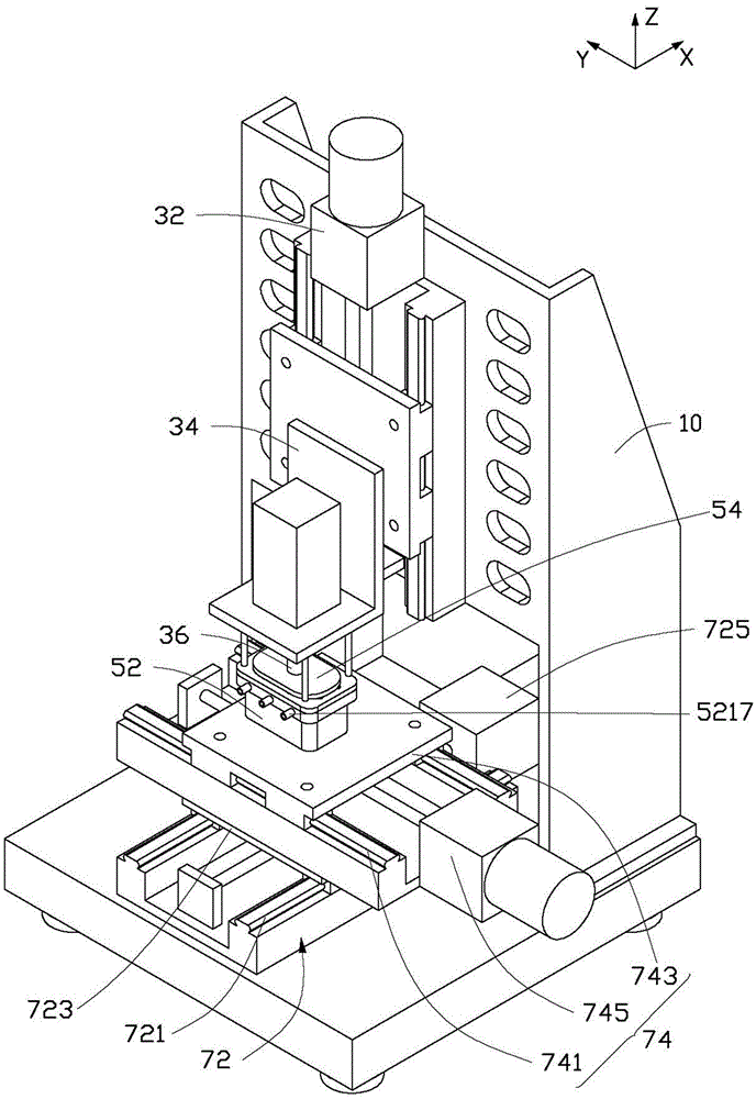
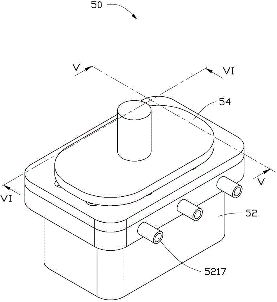
[0017] see figure 1 and Figure 7 , the electrolytic machining device 100 of the present invention is used to process and form a deep cavity 310 on a workpiece 300 and effectively discharge the electrolysis product 500 in the machining gap 600 . The electrolytic processing device 100 includes a fixed frame 10 , a feeding assembly 30 , a liquid supply pump 40 , an electrode assembly 50 , a moving assembly 70 , an electrolytic tank 80 and a vacuum pump 90 . Both the feeding assembly 30 and the moving assembly 70 are fixed on the fixing frame 10 and arranged opposite to each other. The electrode assembly 50 is fixed on the feed assembly 30 , and the feed assembly 30 can drive the electrode assembly 50 to reciprocate along the Z-axis direction. The electrolytic tank 80 is fixed on the moving component 70 , and the moving component 70 can drive the electrolytic tank 80 to move along the X-axis direction and the Y-axis direction perpendicular to the Z-axis direction. The vacuum p...


PUM


Abstract

An electrochemical machining apparatus includes a fastening bracket, a first drive member positioned on the fastening bracket, a connecting member, a first electrode connected to the connecting member, a second driving member, a second electrode connected to the second driving member, a moving assembly positioned on the fastening bracket, an electrolytic cell positioned on moving assembly, a pump, and a vacuum pump. The first electrode defines a plurality of liquid collecting grooves spaced from each other. Each liquid collecting grooves defines a plurality of second through holes. At least one liquid collecting groove is connected to the pump, and the other liquid collecting grooves are connected to the vacuum pump. The portion of the second electrode can be inserted into and depart from the second through holes.

Description

technical field [0001] The invention relates to an electrolytic machining device, in particular to an electrolytic machining device for machining and forming a deep cavity. Background technique [0002] During Shaped tube electrochemical drilling (STED), the electrolyte flows out at high speed from the cathode of the tool, that is, the hollow metal tube (round tube or special-shaped tube), and fills the entire machining gap. The cathode of the tool is fed, and the anode of the workpiece is dissolved under the action of the electrochemical reaction and gradually forms a hole shape consistent with the cross section of the metal tube, and the electrolyte takes the electrolysis product out of the processing area. [0003] When the electrolyte is a neutral salt solution, the electrolytic product is a flocculent insoluble substance. If the flocculent product cannot be discharged in time, it will instantly conduct the cathode and anode, causing spark discharge or even a short circu...

Claims


Application Information

Patent Timeline
IPC IPC(8): B23H3/00B23H3/10
CPCB23H3/00B23H3/10B23H3/04B23H7/30C25F7/00
Inventor 章绍汉
Owner 富联精密电子(郑州)有限公司
Why Eureka
Try Eureka