Laser marking control method, laser marking head and laser marking machine

A technology of laser marking head and laser marking machine, applied in the field of laser marking head, laser marking machine and laser marking control method, can solve the problem of large open space, occupying a lot of space, and the laser marking machine cannot realize marking problems such as standard operation to achieve the effect of large span and small volume

Active Publication Date: 2015-05-20
MAXPHOTONICS CORP
View PDF5 Cites 15 Cited by
  • Summary
  • Abstract
  • Description
  • Claims
  • Application Information

AI Technical Summary

Problems solved by technology

The method of controlling the deflection of the laser beam by controlling the reflection angle of the mirror requires a large open space, which makes the laser marking head too large and takes up a lot of space. In addition, due to the limitation of the reflection angle, the laser The marking machine cannot achieve large-format marking operations

Method used


Image

  • Laser marking control method, laser marking head and laser marking machine
  • Laser marking control method, laser marking head and laser marking machine
  • Laser marking control method, laser marking head and laser marking machine

Examples


Embodiment Construction

[0021] The present invention will be described in detail below in conjunction with the accompanying drawings and embodiments.

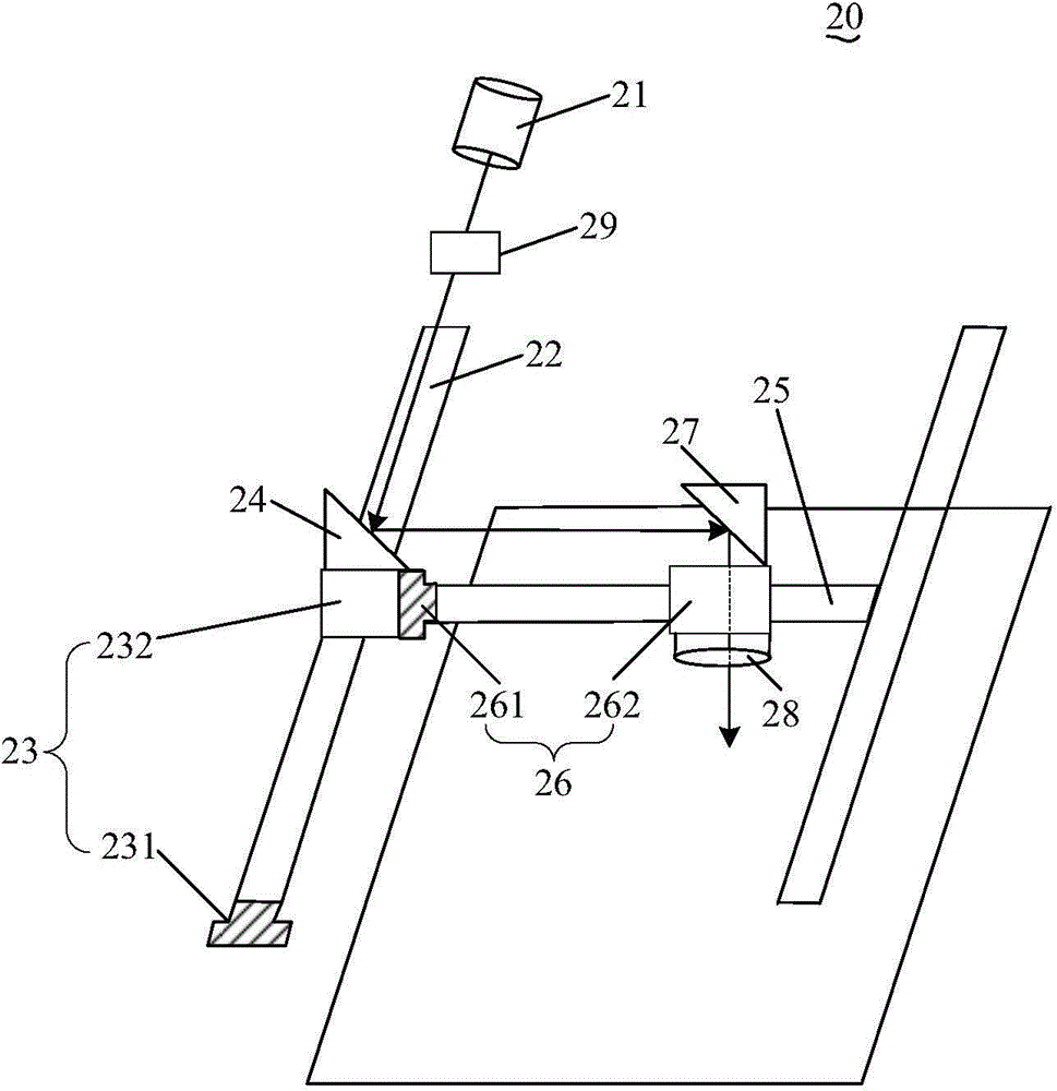
[0022] see figure 1 , the laser marking head 20 includes a laser generator 21 , a first guide rail 22 , a first slide device 23 , a first reflector 24 , a second guide rail 25 , a second slide device 26 and a second reflector 27 .

[0023] The first sliding device 23 is sleeved on the first guide rail 22, and the first sliding device 23 can slide along the first guide rail 22, the first reflector 24 is fixed on the first sliding device 23, and the second guide rail 25 is fixed on the first On the sliding device 23, the second guide rail 25 is perpendicular to the first guide rail 22, the second sliding device 26 is sleeved on the second guide rail 25, and the second sliding device 26 can slide along the second guide rail 25, and the second reflector 27 is fixed on the On the second sliding device 26, the laser light emitted by the laser generator 21 ...


PUM


Abstract

The invention provides a laser marking control method, a laser marking head and a laser marking machine. The laser marking head comprises a laser generator for emitting lasers, a first guide rail, a first sliding device capable of sliding along the first guide rail, a first reflector fixed to the first sliding device, a second guide rail fixed to the first sliding rail and perpendicular to the first guide rail, a second sliding device capable of sliding along the second guide rail, and a second reflector fixed to the second sliding device. The lasers emitted by the laser generator are parallel to the first guide rail and enter the first reflector in an incident mode, the first reflector reflects the lasers to the second reflector, the lasers reflected by the first reflector are parallel to the second guide rail, the second reflector reflects the lasers downwards, and then marking is positioned. By the adoption of the mode, the laser marking head is smaller in size and capable of achieving large-width and large-span marking operation.

Description

technical field [0001] The invention relates to the technical field of laser control, in particular to a laser marking control method, a laser marking head and a laser marking machine. Background technique [0002] Laser marking machine refers to the equipment that uses laser beams to irradiate objects to evaporate the surface of the object to expose deep substances, so as to engrave patterns, trademarks and text on the surface of the object. According to the laser generation method, the laser marking machine is mainly divided into: carbon dioxide laser marking machine, semiconductor laser marking machine, fiber laser marking machine and so on. [0003] In order to draw exquisite marks on the surface of the object, it is necessary to accurately control the position of the laser output by the laser marking head in the laser marking machine on the object. In the prior art, the laser emitted by the laser generator in the laser marking head is incident on two reflectors, and th...

Claims


Application Information

Patent Timeline
Patent Type & Authority Applications(China)
IPC IPC(8): B23K26/362B23K26/08
CPCB23K26/0643B23K26/0648B23K26/0876B23K26/128B23K26/062B23K26/70B23K26/009B23K26/048B23K26/0869B23K26/10B23K26/36
Inventor 居剑蒋峰
Owner MAXPHOTONICS CORP
Why Eureka
Try Eureka